

Frequently asked questions
Answers on amplifier platforms, software and system configuration.
MyUniverso - Layers, Standards, and Processes
3 questionsDoes PWS encrypt all data transmissions, including web server-to-server data transmissions?
Yes, all the traffic related to the Universo system, including server-to-server communication is encrypted.
What protocol is used for device to cloud communication?
MQTT (Message Queuing Telemetry Transport) is used to communicate with the cloud.
MQTT is an OASIS standard messaging protocol for the Internet of Things (IoT)
An MQTT server verifies that it is connected to the correct client by authenticating the client certificate with the SSL protocol, or by authenticating the client identity with a password
Do I have to open any particular network port on the firewall?
You don't have to open any port in the firewall, the only requirement is that the amplifier can access to the internet.
MyUniverso - Hosted Services
2 questionsWhere is the cloud located?
Currently, MyUniverso is deployed in the West Europe region but we plan to replicate the installation in additional countries\region.
What security framework does utilize? -> Where MyUniverso is hosted?
MyUniverso is hosted in Microsoft Azure cloud platform and rely on the security standard offered by Microsoft.
MyUniverso - Security Testing
3 questionsWhat measures do you have to prevent MyPowersoft account hacking?
After 3 failed authentication tentatives we temporary disable the account that need to be manually reactivated by the end user. We plan to integrate also two factor authentication in our services.
In the event of a data breach, what is incident response process?
In the event of a data breach of a device or an account we can disable the target of the attack to avoid any possible issue. Anyway, all the data stored are not in any way connected and related to a physical person.
How reliable is the service? do you have any high availability reassurances?
Our high availability assurance service relies on Microsoft Azure service.
MyUniverso - Data Security
4 questionsWhat is my role in data protection and security?
It is important to adopt all the best practice related to the security. For instance:
- change your password frequently
- never communicate your password to anyone
- don't share your account information
- don't reply to account reactivation email unless you explicitily requested it
Who owns the stored data?
Powersoft is the owner of the stored data. (TBV with Legal Dept.)
Who can view data in the cloud?
Data in the cloud can only be accessed by authorized personnel. Moreover Powersoft doesn't share any data or information with third party.
What data is stored in the cloud?
We stores telemetries and events related to the amplifier usage. Anyway all the data stored are not in any way connected and related to a physical person.
Network
3 questionsOperation modes
Powersoft amplifiers may feature one or two Dante ethernet ports. Amplifiers with a single Dante port also feature an additional standard Ethernet port, with each port operating independently from one another. In amplifiers where two Dante ports are available (labelled primary and secondary), it is possible to switch between different operation modes: Switched Mode
The secondary Dante port behaves as a standard switch port, allowing daisy-chaining through the amplifier (Figure 4). This is the default configuration for Powersoft amplifiers with two Dante ports.
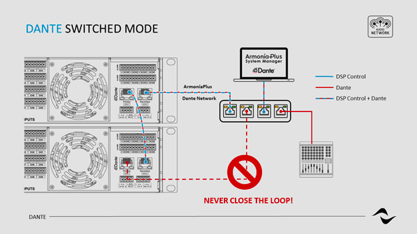
Figure 4 – Example of Dante Switched Mode configuration with Powersoft amplifiers.
Split Mode For amplifiers with a single Dante port and one Ethernet port, this is the default and only operation mode available. In amplifiers with two Dante ports, ‘Split Mode’ can be selected, allowing the primary port to behave as a regular Ethernet port operating independently from the Dante network (Figure 5).
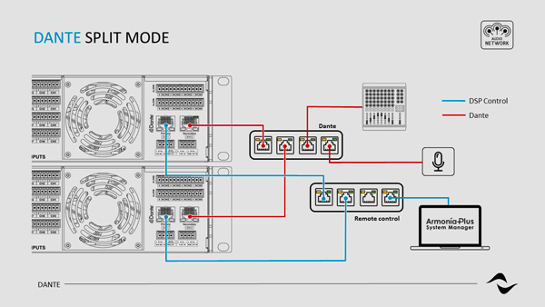
Figure 5 – Example of Dante Split Mode configuration with Powersoft amplifiers.
Redundant Mode When an amplifier is set to ‘Redundant’, it will duplicate the Dante audio traffic to both Dante ports, allowing the implementation of a redundant network via the secondary port (Figure 6).
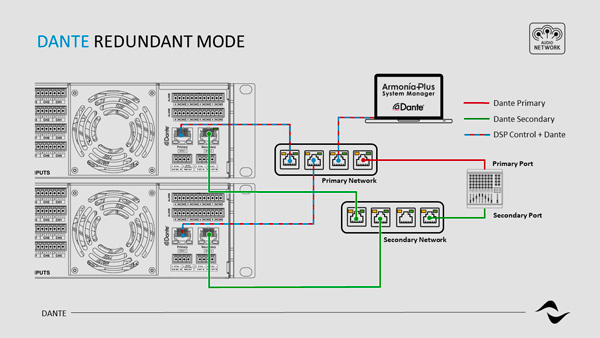
Figure 6 – Example of Dante Redundancy Mode configuration with Powersoft amplifiers.
Table 1 below provides a list of all Dante-enabled Powersoft amplifiers and their possible port configurations.
- 2x Dante Ports (Switched/Split/Redundant) - 1x Dante + 1x Ethernet (Split Mode only) - 2x Dante Ports (Switched Mode only)
- Ottocanali Series - 12K4 DSP+D - ✓
- 8K4 DSP+D - ✓
- 4K4 DSP+D - ✓
- Quattrocanali Series - 4804 DSP+D - ✓
- 2404 DSP+D - ✓
- 1204 DSP+D - ✓
- Duecanali Series - 4804 DSP+D - ✓
- 1604 DSP+D - ✓
- 804 DSP+D - ✓
- X Series - X4 - ✓
- X8 - ✓
- T Series - 302 - ✓
- 304 - ✓
- 602 - ✓
- 604 - ✓
Table 1 – List of Dante-enabled Powersoft amplifiers. To toggle between the different operation modes in amplifiers with two Dante ports:
- Open the ‘Device View’ window by double-clicking on the device to be configured.
- Click on the ‘Network Config’ tab (Figure 3).
- Under ‘Switch Configuration’ select the desired operation mode from the drop-down list.
Following the above operation, a device reboot is necessary for changes to take effect. Please take extra care when changing the amplifier’s settings from split or redundant modes back to switched mode. All Powersoft amplifiers with two Dante ports are set to operate in switched mode by default. When changing from split or redundant modes back to switched mode, two different networks may be unintentionally bridged causing problems such as uncontrolled network flooding. Additionally, when setting up a redundant network, all equipment such as switches and cables must be duplicated. The primary and secondary networks MUST NOT be interconnected at any point.
Connecting Powersoft amplifiers to a Dante Network
Physical connection to a Dante network is done via regular Cat5e (or higher) wiring. If a switch is used, special attention should be given to its capabilities, as certain products are not compatible with Dante Networks. For maximum reliability, network switches shall:
- be Rated for Gigabit Ethernet.
- be non-blocking.
- have Quality of Service (QoS) with at least four queues.
- have Diffserv (DSCP) QoS with strict priority;
- not have or have EEE (Energy efficient ethernet) switched off.
Switch Requirements For more information onswitch requirementsfor Dante compatibility, and on how to create and manage Dante networks, please refer to Audinate’swebsite. When opening the ‘Dante Controller’, all devices connected to the Dante network will be displayed in the list of transmitters and receivers (Figure 1).
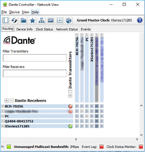
Figure 1 – Dante Controller Network View window.
If the computer in use features multiple network ports, in some instances, ‘Dante Controller’ may connect to the wrong one. To overcome this issue, click on the square next to ‘P:’ at the bottom left corner of the ‘Network View’ window. This will open the Dante interface configuration window (Figure 2), from where the correct port can be selected.
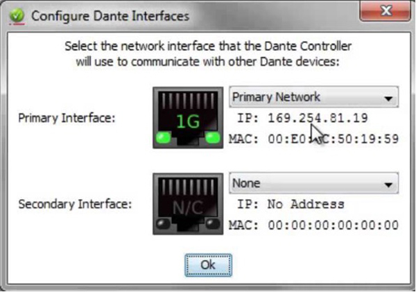
Figure 2 – Configuration of Dante interfaces.
Powersoft amplifiers connected to the Dante network will automatically obtain IP addresses by default, and in most circumstances, there is no need to change the address settings. However, static IP addresses can be assigned if necessary. To assign a static IP address:
- Open the ‘Device View’ window by double-clicking on the device to be configured.
- Click on the ‘Network Config’ tab (Figure 3).
- Under ‘Addresses’ switch to the option 'Manually configure an IP Address'
- Enter the IP Address and Netmask.
- Click ‘Apply’.
The DNS Server and Gateway settings are optional - the device will use network defaults if they are not specified. To revert to the previous settings, click ‘Revert’. It is important to note that this operation requires a device reboot. This can be done by simply clicking ‘Reboot’ under ‘Reset Device’. However, in some instances, it has been verified that a manual reboot of the amplifier is necessary for modifications to take effect and is therefore recommended as best practice.
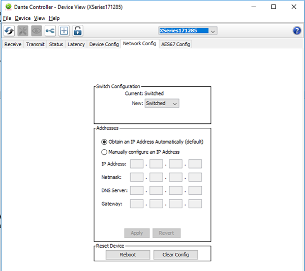
Figure 3 – Dante Controller ‘Network Config’ tab in the ‘Device View’ window.
Please note that when Powersoft amplifiers are set to automatically obtain IP addresses, Dante Controller must be running on a host computer also configured to obtain IP addresses automatically. Likewise, for static IP address configurations, fixed IP addresses must be assigned to both host computer and amplifier, with both devices operating within the same subnet.
Dante setup and configuration
All Powersoft amplifiers featuring a Dante card can be set up to send and/or receive audio on a Dante network. This type of connection utilises standard IP networks to transmit high-quality, uncompressed audio, with near-zero latency.
All Powersoft DSP+D products will require two different network IP addresses: one for controlling the amplifier’s DSP and one for the Dante network.
The configuration and routing of Powersoft amplifiers in a Dante network can be entirely done via ArmonìaPlus or using Dante Controller, provided by Audinate.
In a Dynamic Music Distribution system, the configuration must be done using ArmonìaPlus and source patching will be automatically managed by the DMD itself (see Dynamic Music Distribution Desing Guide for more info).
The Dante modules in Powersoft amplifiers operate with their own dedicated Firmware. It is recommended that all modules in a Dante environment are always updated, i.e., running the latest firmware not just on the amplifiers, but in all the connected devices. This best practice will help to improve system performance and compatibility.
More information on how to update the Dante firmware in Powersoft amplifiers can be found on Powersoft’s website.
Switch Configurations
6 questionsEnabling and configuring IGMP snooping
To enable IGMP Snooping in the Cisco switch, for when multicast traffic is necessary:
From the main switch configurations page, using the left-hand side menu, follow the path ‘Multicast > Properties’ (Figure 12).
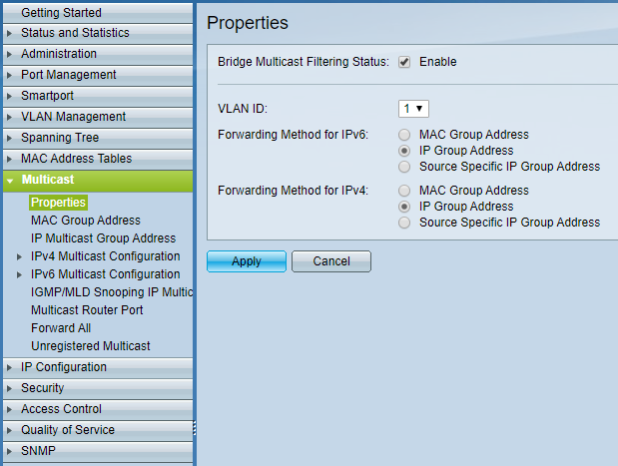
Figure 12 – Setting up multicast properties.
Tick the enable check box for ‘Bridge Multicast Filtering Status’. Under ‘VLAN ID’, select the VLAN for which multicast traffic will be used. If no VLANs have been configured, select 1. SelectIP Group Addressfor both ‘Forwarding Method IPv6’ and ‘Forwarding Method IPv4’. Next, go to ‘Multicast > IPv4 Multicast Configuration > IGMP Snooping’ (Figure 13).
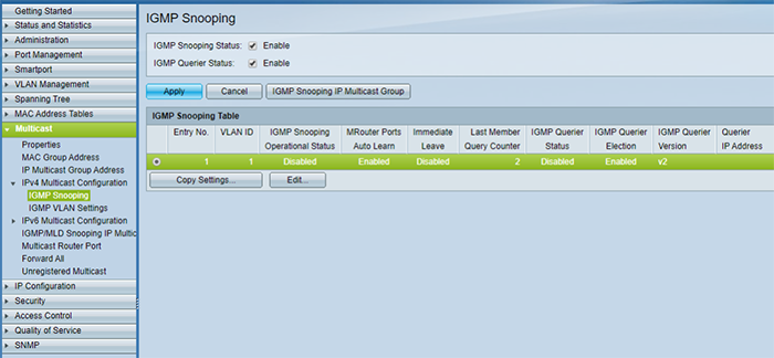
Figure 13 – Enabling IGMP Snooping.
Select the enable check box for both ‘IGMP Snooping Status’ and ‘IGMP Querier Status’ and click ‘Apply’. To edit the IGMP Snooping settings, still on the same page, under ‘IGMP Snooping Table’, select the multicast VLAN ID and click ‘Edit’. This will open the ‘Edit IGMP Snooping’ window (Figure 14).
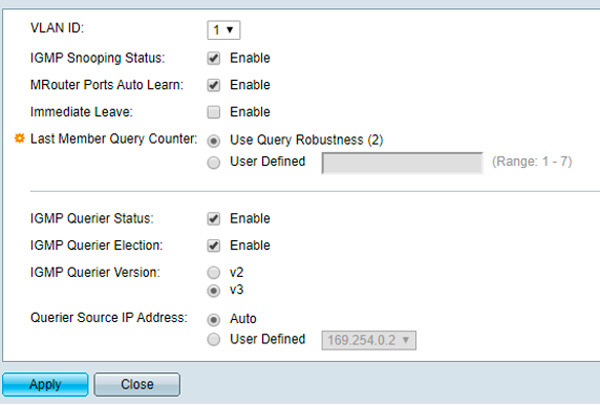
Figure 14 – IGMP Snooping Settings.
Make sure the ‘IGMP Snooping Status’ is enabled, as well as ‘MRouter Ports Auto Learn’. Next, enable the ‘IGMP Querier Status’, ‘IGMP Querier Election’, set the ‘IGMP Querier Version’ toIGMPv3,and click ‘Apply’. This is a recommended setting. As mentioned previously, Dante and AES67 both support IGMPv2 and IGMPv3. The important thing is that all switches in the network are configured to run on the same version.IMPORTANT NOTE:Remember from the previous sections of this document that in networks using multiple switches, it is safer to have only one IGMP Querier enabled, preferably on a switch sitting close to the root of the network topology. In this case, the functions in step 9 above should be disabled for all switches down in the connection chain and that will not operate as IGMP Queriers.
Disabling Energy Efficient Ethernet (EEE)
To disable EEE in the Cisco switch:
From the main switch configurations page, using the left-hand side menu, follow the path ‘Port Management > Green Ethernet > Properties’ (Figure 11). Untick the ‘802.3 Energy Efficient Ethernet (EEE)’ enable box and click ‘Apply’.
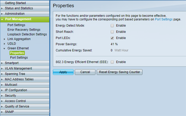
Figure 11 – Disabling EEE.
DSCP configuration for QoS management
To configure DSCP parameters:
From the main switch configurations page, using the left-hand side menu, follow the path ‘Quality of Service > General > QoS Properties’ and enableQoS Advanced Mode(Figure 8).
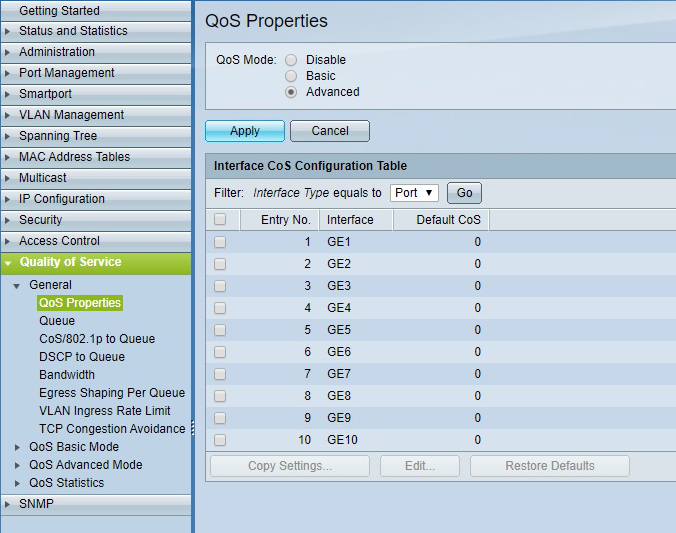
Figure 8 – Enabling QoS Advanced Mode.
It is then necessary to change the settings from Layer 2 CoS management to Layer 3 DSCP. Under ‘Quality of Service > QoS Advanced Mode > Global Settings’, selectDSCPas the ‘Trust Mode’,Trustedas the ‘Default Mode Status’, and click ‘Apply’ (Figure 9).
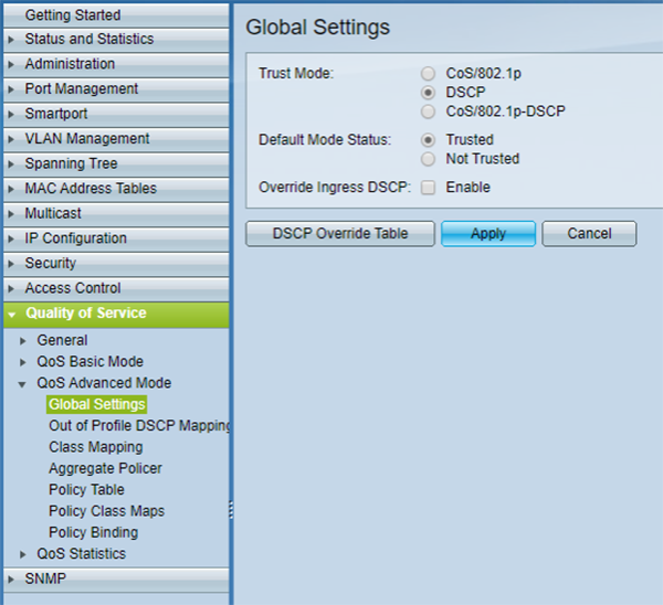
Figure 9 – Global settings configuration.
Next, go to ‘Quality of Service > General > DSCP to Queue’, specify the priority output queue of each DSCP label, and click ‘Apply’ (Figure 10). In Cisco switches, queue number 1 has the lowest priority, while queue 4 has the highest. The labels to which a priority must be given depending on the type of audio network in use.
- For Dante-AES67 (non-Audinate)
- 56 (CS7) - 4 - 46 (EF) - 4
- 46 (EF) - 3 - 34 (AF41) - 3
- 8 (CS1) - 2 - - - 2
- Everything else - 1 - Everything else - 1
IMPORTANT NOTE:Consult your network administrator in case the network presents other pre-existing systems, such as a LAN VoIP, as the settings above may need to be reviewed.
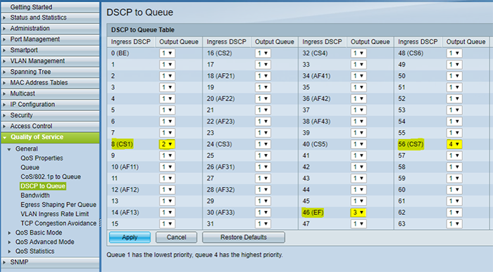
Figure 10 – Configuration of DSCP queues.
Network switch configuration example: Cisco sg300-10
The following is an example of how to configure a Cisco switch with some of the key parameters for a correct Dante/AES67 operation. The configurations page for most switches can be accessed by typing its IP address in any web browser address bar. For this to work correctly, the computer must be in the same IP range/subnet of the switch it is connected to. By default, Cisco switches are in the IP range 192.168.1.X. To change the computer’s IP address and subnet mask, in WINDOWS:
- Connect the computer to any of the switch ethernet ports.
- On a Windows PC, access theEthernet Statuswindow (Figure 4). Usually, this is done from the ‘Network and Sharing Center, by clicking on ‘Ethernet’ from the active networks.
- In the Ethernet Status window, click on ‘Properties’ to open theEthernet Propertieswindow, select ‘Internet Protocol Version 4 (TCP/IPv4)’, and click ‘Properties’ (Figure 5).
- In theTCP/IPv4 Propertieswindow, select ‘Use the following IP address to configure a static IP address for the PC (Figure 6).
- Type in an IP address following 192.168.1.X; where X can be any number from 1 to 253, assuming there are no other devices in the same subnet connected to the switch for which one of those numbers has already been allocated.
Under Subnet Mask, type in 255.255.255.0, and click ‘OK’.
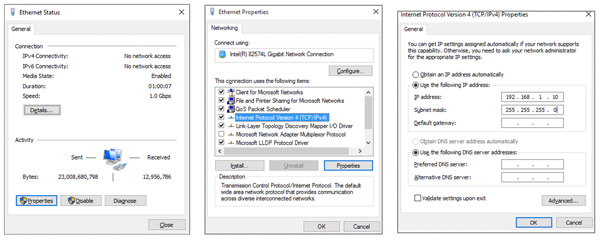
Figure 4 – Ethernet Status window. Figure 5 – Ethernet Properties. Figure 6 – TCP/IPv4 Properties.
After the configuration of the switch is done, remember to revert the operation by selecting ‘Obtain an IP address automatically from theTCP/IPv4 Propertieswindow and clicking OK. Once both the computer and the network switch are on the same subnet IP range:
Open any web browser on the computer and type the IP address of the switch in the address bar. By default, Cisco switches use the IP address 192.168.1.254. This should open the switch configurations page (Figure 7). Type in the requested username and password. The default for the SG350-10 is “cisco” for both fields.
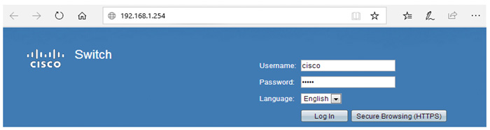
Figure 7 – Ethernet Status window.
Once connected to the switch and logged into the configurations page, it will be possible to access and adjust each one of the configuration parameters.
Recommendations for multicast traffic
The following switch configurations apply to networks containing multicast data traffic. Dante devices may be configured to transmit either unicast or multicast audio streams, while AES67 only works with the multicast transmission. For Dante, unicast data traffic will require fewer switch and routing configurations, making it a simpler and faster solution for small and dedicated networks, under normal circumstances. However, in larger scenarios, and especially where multiple devices receive the same audio stream, the use of multicast over unicast for audio transmission may be beneficial. If correctly configured, multicast can be more efficient than unicast in terms of bandwidth consumption. For maximum multicast efficiency and reliability, it is recommended that network switches have:
IGMP Snooping Activated– When using multicast traffic, it is important to configure the network accordingly to increase efficiency and reduce bandwidth consumption. Without a proper configuration to manage this traffic, multicast packets will be broadcast to all receivers in the domain, including devices that have not requested those packets (Figure 2). This could be a problem for some amplifiers that may not be able to manage a high count of incoming data packets. To overcome this issue,IGMP Snoopingmust be activated in the network switch. Internet Group Management Protocol (IGMP) is a communication protocol used to establish multicast groups and manage memberships of receiving and transmitting devices. When a multicast transmission starts, a multicast group is created and an announcement is sent to all devices over the network, after which devices wishing to receive the multicast packets will send IGMP to join messages, specifying the IP multicast group they want to join.IGMP Snoopingis the process where the network switch examines the IGMP communications between devices to create a table with what multicast packets are needed and in which of its ports. In this process, the switch will only forward multicast data packets to the designated ports and receivers (Figure 2).
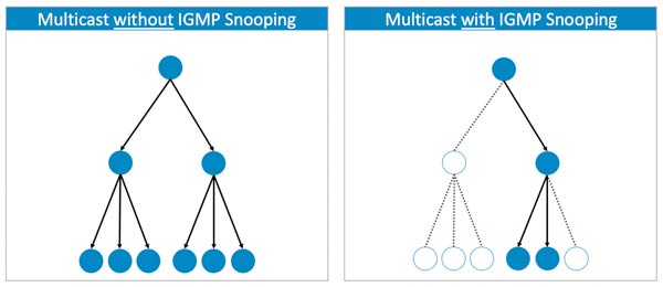
Figure 2 – Difference between multicast packet transmission with and without IGMP Snooping in operation.
For the purpose of a stable IGMP Snooping operation, anIGMP Snooping Queriermust also be enabled. The aim of a querier is to keep the table with all the multicast group memberships up to date. It sends out IGMP queries at a timed interval to all members belonging to the IP multicast group. All devices wishing to remain in the group must reply to the query with a confirmation. Those devices that do not respond within a defined amount of time will be removed from the group’s table and will no longer be forwarded to those multicast streams. Although a network can accommodate multiple IGMP Snooping Queriers (and will automatically select one), it is safer to have only one IGMP querier enabled, preferably on a switch sitting close to the root of the network topology. Some switches also allow the configuration of a ‘Query Interval’, which is related to the group membership timeout and is the number of seconds that must pass before the switch determines that no more members of a multicast group exist on the network. When the ‘Query Interval’ is large, the time required for the multicast stream to start or stop working becomes longer and the user may experience that an amplifier will take longer to start playing audio. An example of IGMP Snooping configuration for a Cisco switch is given later in this document. Finally, IGMP has three different versions: v1, v2, and v3. However, IGMPv2 supports IGMPv1, and IGMPv3 supports IGMPv2. Although not all features of an earlier version of IGMP are supported, the features related to membership query and membership report messages are supported for all IGMP versions. For Dante and AES67, IGMPv2 or IGMPv3 are recommended.Final RecommendationsThe following are general recommendations for consideration, especially in the case of larger networks:
Topology– Although “daisy chaining” may be suitable for connecting devices in a network, the failure of any device in the chain will break connections to devices further down in the “stream”. In general, switched networks are best thought of when using a “star”, or “hub and spoke” topology. In such a setup, all devices on a star are connected to a single switch and, if any device fails, the others continue to communicate. As the network gets larger, additional switches may be brought in to extend the network. The star topology can be easily extended in a multiple-star arrangement to suit larger systems (Figure 3).
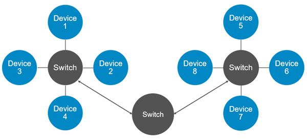
Figure 3 – Example of a multiple-star topology, where no device is more than 4 “hops” away from any other.
Cabling– Any type of ethernet cable is suitable for a Dante or AES67 network, although in a gigabit-speed network CAT5e or CAT6 cables are recommended. CAT6 cables are rated for greater noise resistance in electrically noisy environments, however, CAT5e is enough for most applications. The maximum allowed length for a normal ethernet cable is approximately 100m. For longer distances, fiber optics will be necessary, as it can run for several kilometers when required. The drawback is that fiber connections will require network interfaces that can support them, such as Small Form-Factor Pluggable (SFP).
Dante & AES67
This document aims to provide general recommendations and configurations for network switches to be used with Powersoft amplifiers for Dante and AES67 connectivity, including examples. For remote control and monitoring of amplifiers, any type of network switch running on at least 100 Mbps will be sufficient. However, for transport of audio over IP via Dante or AES67, dedicated network switches and configurations may be necessary. This is especially the case in large and heavily loaded or mixed, networks (e.g., audio + other data types). For maximum Dante and/or AES67 network reliability, it is recommended that switches be/have:
- Rated for gigabit Ethernet– although 100Mbps may be enough for a small and audio-dedicated network, larger and heavier installations may require a switch running on at least 1Gbps.
- Non-blocking– in this type of device (almost every switch nowadays), all ports can run at full speed without any loss of data packets. The switch can handle the total bandwidth on all ports, establishing routing to any free output port without interfering with other traffic.
- Managed– differently from unmanaged switches (plug-and-play), managed switches offer a series of different options and adjustments, such as the ability to prioritise the transport of certain types of data over others, and creating Virtual Local Area Networks (VLANs), which are particularly important in mixed networks where audio is combined with other types of data. For small and audio-dedicated networks, unmanaged switches may be sufficient for Dante and AES67 operations. However, in heavily loaded networks, or where audio streams share the network with other data (e.g., video, security, etc.), a managed switch will likely be necessary.
- Quality of Service (QoS) management– only available in managed switches. QoS network management allows the switch to prioritise certain types of data packets over others. Such packets get preferential treatment and are “moved to the front of the line" ahead of other traffic (Figure 1). In the case of audio streams, the priority must first be given to clocks for device and audio signal synchronization, followed by the audio packets themselves. This is to guarantee low-latency and high-quality audio streams across the network. Dante networks require at least four priority queues, whilst AES67 only requires three.

Sketch of different priority queues for audio data management in an AES67 network.
- Differentiated Services Code Points (DSCP) QoS– DSCP is a type of QoS management. In order to prioritise the different packets of information, Dante/AES67 networks use DSCP labels and numbers to organise these packets in different priority queues. Such management is done by the switch and, therefore, where managed network switches are necessary, these must work with DSCP QoS. Many switches have Layer 2 “CoS QoS” management enabled by default, and this configuration needs to be changed to Layer 3 “DiffServ/DSCP QoS”. Once enabled, check the priority assignments. The switch will require a special configuration to recognise and prioritise the specific DSCP values used by Dante (Table 1) and by AES67 (Table 2). A configuration example is covered later on in this document.
- PRIORITY QUEUES-USAGE-DSCP LABEL-DSCP NUMBER
- 1. High - Clock synchronization - CS7 - 56
- 2. Medium - Audio packets - EF - 46
- 3. Low - (Reserved) - CS18 - 8
- 4. None - Other packets - Best-Effort - 0
Table 1 – Dante’s different priority queues and their respective DSCP values.
- PRIORITY QUEUES-USAGE-DSCP LABEL-DSCP NUMBER
- 1. High - Clock synchronization - EF - 46
- 2. Medium - Audio packets - AF41 - 34
- 3. None - Other packets - Best-Effort - 0
Table 2 – AES67’s different priority queues and their respective DSCP values.
In mixed networks with Dante and AES67 streams generated from a Dante card, it is always recommended that the DSCP values from Table 1 are used, and that clock synch packets always receive the highest priority treatment. The values in Table 2 should only be used in AES67 networks that do not contain Dante streams.IMPORTANT NOTE:In larger Wide Area Network (WAN) connections, such as those used in large corporate environments, DSCP tags may not be respected by edge routers. Consult your network administrator to discuss options to bypass this constraint if it exists.
- EEE (Energy Efficient Ethernet) DISABLED– switches that do not have energy efficient or energy save modes do not require any additional configuration. However, this function needs to be disabled in switches that offer it, as it will impede proper operation of low-latency audio over IP. The energy-save function tends to delay packets sent over the network. EEE is also sometimes referred to as ‘Green Ethernet’ or ‘IEEE 802’. An example of turning EEE off in a Cisco switch is given later in this document. Beware that some unmanaged switches have EEE enabled by default and will not allow the user to disable this function.
Speaker Preset
15 questionsRun Armonía Plus on Mac - Discovery the Amplifiers
We are now ready to click on ‘Design>Match’and select 'Discovery' to view all the amplifiers connected to the network.
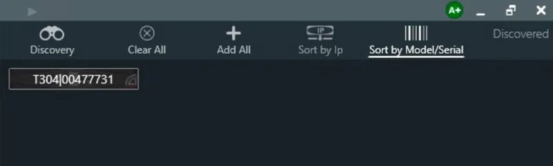
Discovery
Run Armonía Plus on Mac - Communication Manager
Once the network is enabled you need to go on ‘Communication manager’ in Armonía Plus and choose thenetworkwhere the amplifiers are connected, in our example:
- EthernetIPaddress169.254.x.x
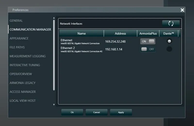
Communication Manager
Run Armonía Plus on Mac - Network configuration on Windows
Next, go to Windows Preferences/Configurations and select the sources for Networks 1 and 2.
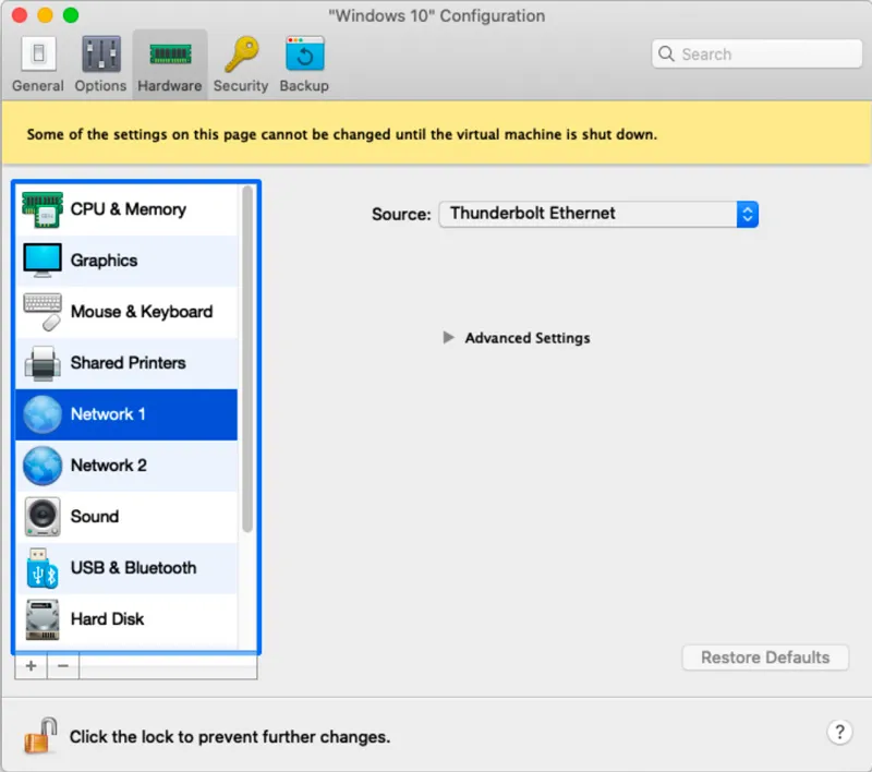
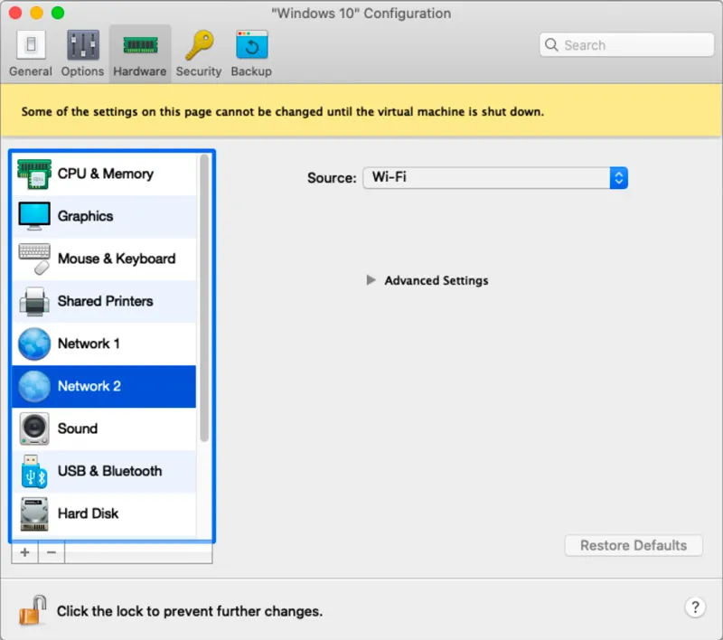
For Network 1, select the Ethernet Adapter. For network 2, selectWi-Fi
Run Armonía Plus on Mac - Network configuration on Mac
Next, set up the network on your Mac. Go toSystemPreferences, thenNetwork.
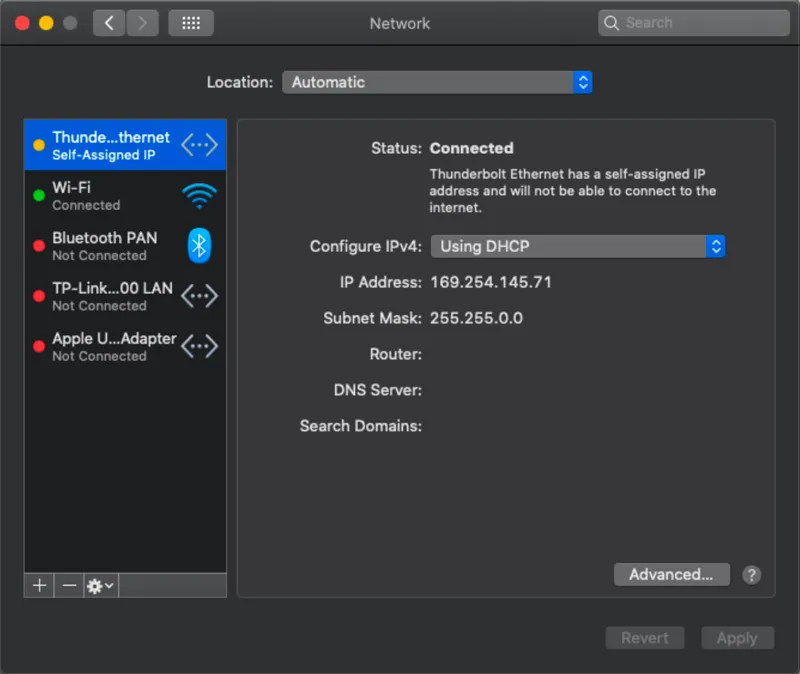
System Preferences > Network > Ethernet
Anethernetadaptershould already appear in the list of networks if inserted, if not, just click on the+button and add a new network. We recommend using the originalAppleThunderboltEthernet adapter. Enable yourMac’sWi-Fi, which will then be shared with the Windows partition, allowing you to update Armonía Plus and use all the services that need internet.
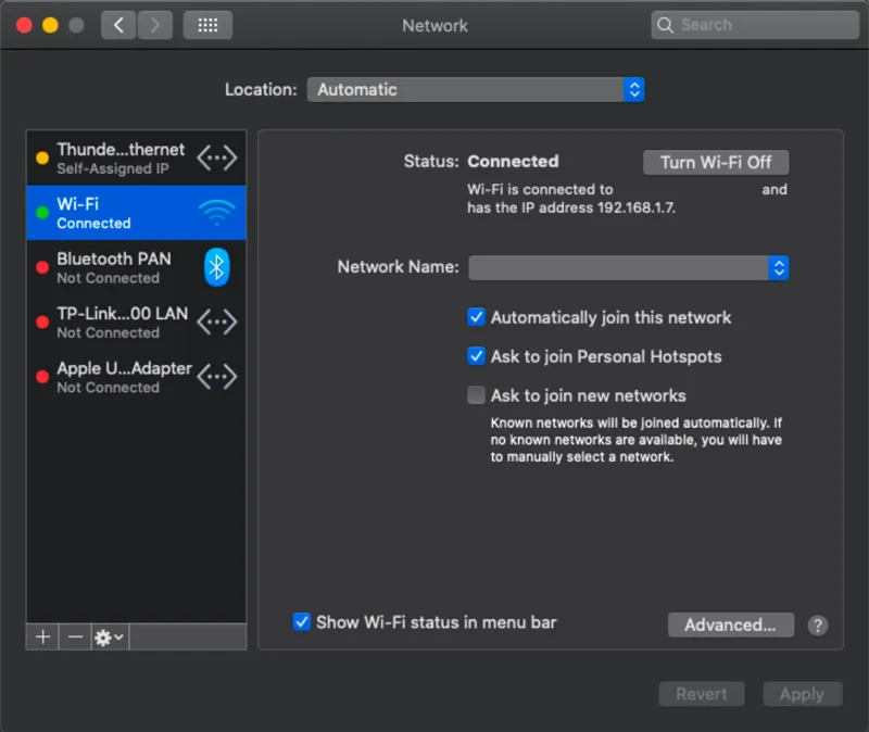
System Preferences > Network > Wi-Fi
Run Armonía Plus on Mac - Download & Install
Parallels Desktop or other virtualization software for Windows.
Armonía Plus, you can find the latest version on com
Run Armonía Plus on Mac
In this application note we will explain how to use Armonía Plus on your Mac through Windows virtualization software. The procedure is fundamentally the same for the various software’s in the market and for our example we will use Parallels Desktop.
How to calculate limiter values
To calculateVoltagethresholds, attack, and release time for the three basic limiters available in ArmonìaPlus, Powersoft has developed a tool called thePowerSharingTool. In this tool, there is a dedicated section called “SuggestedLimiters threshold” that can be used as asafestarting point while working with limiters. Simply add the loudspeaker’sAESpower, and the nominal impedance and select its profile (or the way of the loudspeaker). Once these values are specified the tool will calculate and suggest a possible limiters configuration. The tool provides calculations for bothLow-Z loudspeakersandHi-Z lines (100V, 70V, and 25V) Remember that this is only the starting point, especially for a multi-way loudspeaker where it is always suggested to analyze the behavior of the ways with a musical or pseudo-musical signal. In this way, tonality unbalances due to wide differences in gain reduction between thetransducerscan be avoided.
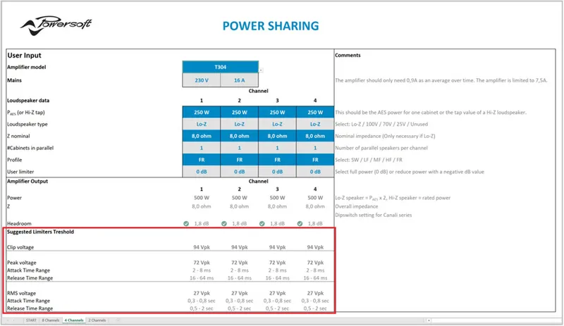
Powersoft Power Sharing tool limiters section.
After this basic analysis of Powersoft limiters we can focus on two key points: the first one is that all Powersoft limiters are made to protect the loudspeaker, so it is best practice to have them always enabled. The second one concerns the sound quality and good system design: the best performances in audio quality are achieved when, as mentioned previously, RMS limiters can do the heaviest part of the job in terms of gain reduction, then Peak limiters to control transients and Clip limiters as a final safety point. By following this simple workflow, you will achieve the best audio quality from your system, ensuring its long lifespan.
How Powersoft limiters work - Clip Limiter
The Powersoft clip limiter is a “brickwall” limiter that blocks the driving signal, not allowing it to exceed the threshold. This limiter has a fixed attack time of 0.3 ms with a lookahead of 0.3 ms that allows anticipating peaks before they occur and therefore with the benefit of less distortion by not having a hard clip. Clip limiters are very fast and are the last safety tool that can be used to avoid loudspeaker damage. To achieve the best result in quality and performance, it is suggested a gain reduction between 0 and 3 dB and engage also Peak and RMS limiters.
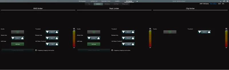
Limiters (basic) in ArmonìaPlus.
How Powersoft limiters work - Peak Limiter
The peak limiter avoids potentially dangerous displacement of the cone (larger excursion with respect to the allowed values), and it is based only on the quantity of signal that is sent through that channel.
Peak limiters, as well as RMS and Clip limiters, are independent from the number of parallel wired speakers: you can use the power and impedance of a single speaker or the power and impedance of the parallel circuit, the given result will be the same.
Pushing into a peak limiter can reduce the crest factor, thus “ squashing ” the dynamics of the original signal. For most applications, 3 to 9 dB of gain reduction is usually suggested.
How Powersoft limiters work - RMS Limiter
The RMS limiter is intended to prevent burning the driver’s voice coil, while at the same time exploiting their maximum performance. The RMS limiter should not be engaged at normal working levels since a common musical signal has very high peaks, but a rather small average level.
Limiter Parameters - Soft Knee
A soft knee slowly increases the compression ratio as the level increases, this way the changing from un-compressed to compressed sound is less audible. This value in Powersoft limiters is expressed in dB below the threshold.
Limiter Parameters - Release Time
It is the time that the gain takes to go from the maximum reduction to 30% of reduction. In general, the release time, must be adequate to avoid a pumping effect and protect the speaker. The release time can be set between 1 to 32 times the attack time.
Limiter Parameters - Attack time
It is the time the limiter takes to get 70% of the total required reduction after exceeding the threshold level. In applications where we want to avoid speaker damage, the longer the attack time, the higher the risk of damaging the equipment. However, settings with a too fast attack time can generatedistortionsor a deep modification to thetransientof thesignal, especially with percussive sounds, resulting in poor perceived sound quality. Typically, a good compromise is to set an attack time no longer than the lowest frequency you need to protect (i.e., 1 ms for an HF driver with X-over at 1kHz octave band).
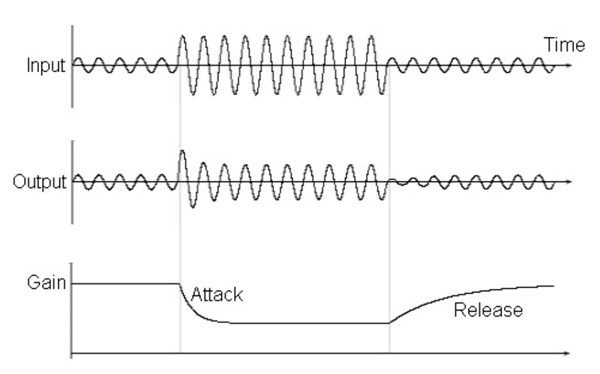
Limiter acting on an audio signal
Limiter Parameters - Threshold
When the input signal level exceeds the threshold, the limiter starts to reduce the input gain. Gain is reduced of an amount equal to the overshoot of the input signal with respect to the threshold.
The threshold value is expressed in Volt because it depends on the power of the loudspeaker and its impedance
Limiting, Speaker Damage and Power Compression
The limiting process insoundreinforcementis a way toprotect loudspeakersfromaccidentaldamage; therefore, limiters are a safeguard against excessivesignalpeaksand/or signal long-term average power. Bear in mind that limiting does not only prevent occasional damage, but it first and foremostguarantees a long loudspeaker life. Speaker limiter designers do not usually concentrate on coloring sound, but rather onspeakerprotection. Typical applications in the audio chain are:
- Controlling theenergyof a signal.
- Controlling thepeaklevelsof a signal.
- Reducing thedynamicrangeof a signal.
Remember that in sound reinforcement you are dealing with power signal (that means highvoltageandcurrents), so the target with limiters is to protect the drivers from the two main causes of damage:
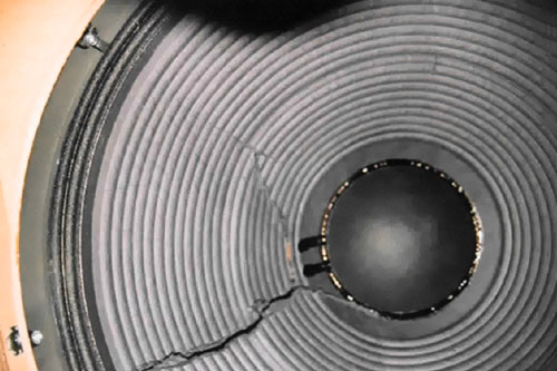
Over-excursion: An impulsive signal can reach the speakers and cause damage due to over-excursion of the voice coil that is driven out of the mechanical limit. This can damage thediaphragmby deforming or breaking it.
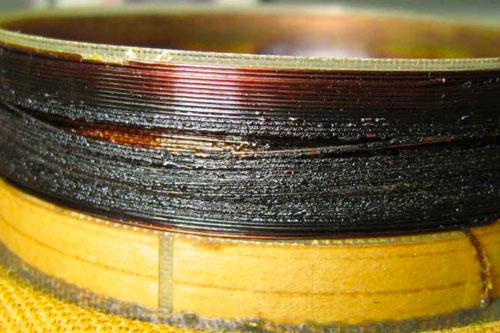
Over-heating: Delivering high power for too much time may lead to overheating of thevoicecoilcopper, the coil former, the magnet, the suspensions, and the cone itself. Another effect is powercompression, more noticeable in low-frequency speakers. When there is power compression there is an increase in the impedance and a decrease in power with the result of less perceived loudness!
Dynamic Music Distribution
14 questionsViews Host failover redundancy
In case a preferred Views Host or WM Touch fails for network or hardware problems, the Dynamic Music Distribution has the Failover Redundancy, which allows the system to continue running using another View Host available on the network. This feature is available starting with WM Touch firmware v1.1.2.9 and Views Host v1.6.4.3. This feature allows seamless failover redundancy across multiple WM Touch and/or PC Views Hosts within the same system. Failover redundancy ensures that the system control will continue to run smoothly even in the case of a WM Touch or PC Views Host failing/going offline. Note that the new failover redundancy does not require any configuration and that the health check of devices within a Dynamic Music Distribution system is a fully automated background process, the onlydifferencewill be theIPAddressof the server because the new Views Host will have a different IP address from the preferred.
Project Properties - Views Host
Design guide chart
The chart below shows some key points that needed to be considered while designing the system for Dynamic Music Distribution.
AMPLIFIER SERIES MAXIMUM ZONES AVAILABLE GPI AVAILABLE DANTE CARD DANTE Input DANTE Output DANTE TX Flows DANTE RX Flows
X8 4 Zones - Brooklyn II 16 8 32 32
X4 2 Zones - Brooklyn II 16 8 32 32
T Series (4 Ch) 2 Zones - Ultimo XT 4 4 2 2
T Series (2 Ch) 1 Zone - Ultimo XT 4 4 2 2
MEZZO AD (2 Ch) 2 Zones 4 Ultimo XT 4 4 2 2
MEZZO AD (4 Ch) 4 Zones 4 Ultimo XT 4 4 2 2
Ottocanali DSP+D 4 Zones - Brooklyn II 16 8 32 32
Quattrocanali DSP+D 2 Zones 4 Ultimo XT 4 - - 2
Duecanali DSP+D 1 Zone 2 Ultimo XT 2 - - 2
Table 4 – Summary of Powersoft amplifier capabilities
Deploying the Armonía Plus project
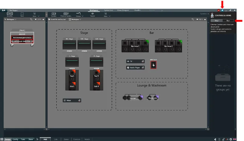
To have zone, source, and scene control on your project, the project needs to “Run” or bedeployedfirst. If the project is not “Run,” the WM Touch will not have the control interface loaded and the WM Passive will only act as aVCAvolumecontrol for your amplifiers. To “Run” the project, you would need to make sure that your project is set up properly. If the project was not set up properly, an error will pop up when you try to run the project. To “Run” the project, click on the “Rocket” icon and then click “Run.”
Runningcontrols&Views
Locating the GPI port
Thediagramsbelow show the location of the “GPI”portof each amplifier.

Figure 1 – Quattrocanali DSP+D GPI port location

Figure 2 – Duecanali DSP+D GPI port location

Figure 3 – MEZZO GPI port location
Notes:Please refer to the Application Notes on how to set up GPI control atwww.powersoft.comor check out our YouTube channel for a tutorial video.
GPI capabilities
Apart from controlling the system using the WM Touch, users can also configure the system to be controlled using the WM Passive wall controllers. The WM Passive wall controllers need to be connected to the “GPI” inputs of an amplifier. Do take note that not all the amplifiers come with “GPI.”
The table below shows the amplifier models and their available “GPI” inputs.
AMPLIFIER SERIES GPI AVAILABLE
X Series
T Series NONE
MEZZO A / MEZZO AD 4
Ottocanali DSP+D NONE
Quattrocanali DSP+D 4
Duecanali DSP+D 2
Table – List of GPI on Powersoft amplifiers
Notes:
The “GPI” signal from one amplifier can be shared over the network with another amplifier. This will enable the user to have WM Passive wall controllers controlling other amplifiers on the network.
While some of the non-DSP+D amplifiers like the Quattrocanali feature “GPI” inputs are used for VCA control. For zone, source, and scene control, a DSP+D enabled amplifier is required.
For MEZZO both A and AD models can have zone, source, and scene control on the “GPI” inputs.
Creating multicast Dante output
DANTE multicast flowsubscriptionsneed to be created fromDANTEController. To do this, the device needs to be online. The multicast flow needs to be created on the transmitter end of the Dante device. To do that, double click on the transmitter and click on “Create a multicast flow” option. For further information, you can always refer to Audinate’s official documentation.
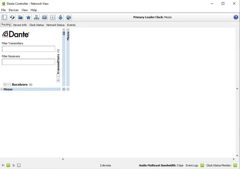
Figure 1 – Selecting a Dante Transmitter
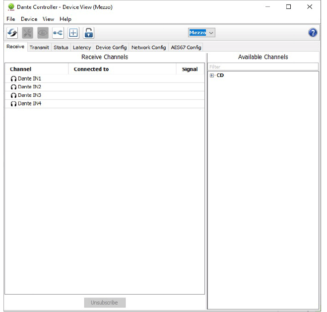
Figure 2 – Create a Multicast Flow Option
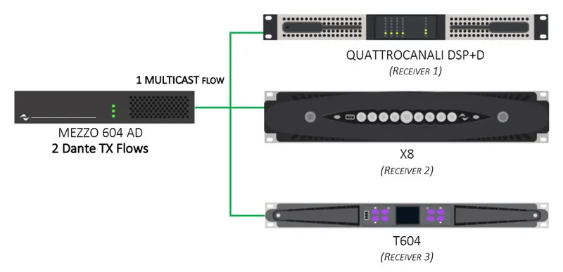
Figure 3 – DANTE Multicast Flow Example scheme
Multicast Dante outputs
By default, patching DANTE outputs of the amplifiers to other devices createunicastflows. In the event that more DANTE devices need tosubscribeto the DANTE outputs, (2 DANTEtransmitterflows for MEZZO AD and T Series and 32 DANTE transmitter flows for Ottocanali) users will find themselves running out of flows for a unicastsubscriptionor find themselves running into a “fan-out”error. Upon finishing “Running” the project, the “Summary” page on Armonía Plus will also indicate that a multicast DANTE flow subscription needs to be created. To create a multicast flow, the user will need to use DANTE Controller.
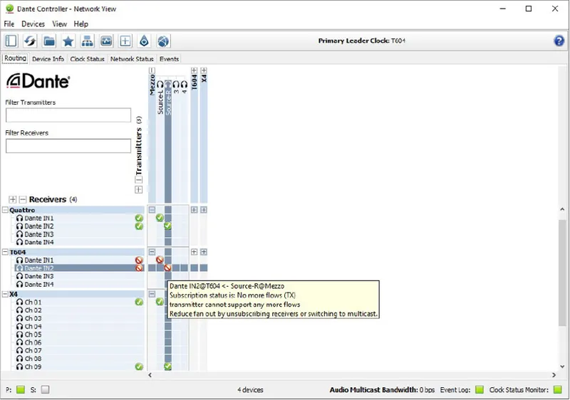
Figure 1 – Dante Controller “No More Flows” Error
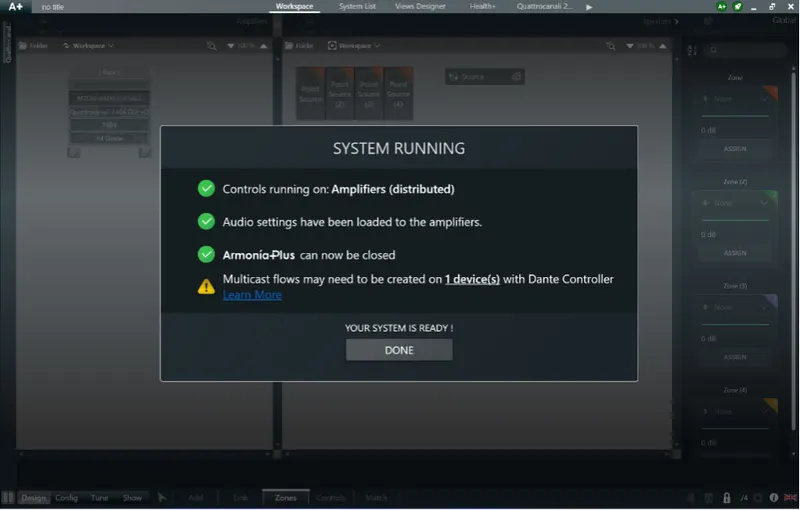
Figure 2 – Armonía Plus Summary PageMulticast Flows Warning
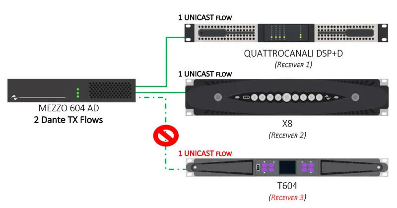
Figure 3 – DanteFANOUTExample scheme
Fanout warnings
Dante Fan Out Warning is now also available. This new feature addresses Powersoft’s Dynamic Music Distribution and that at times designers and installers may experience no audio playback after system deployment.
When designing Dynamic Music Distribution systems based on a Dante backbone it is possible that a unicast Dante source is set to feed more than 4 individual amplifiers at the same time. This will result in Dante fanout error and audio will not be received on all amplifiers.
To address this problem Armonía Plus 2.2 now detects possible fanout conditions during system deployment within the user's design. Upon deployment, a warning is displayed asking users to check the devices at risk as well as direct resources on fixing the problem.
Potential Dante fanout conditions can be addressed even after system deployment by enabling multicast flows on the Dante sources creating the issue within Dante Controller.
Dante overflow
Armonía Plus 2.2 introduces the use of Dante Overflow warnings when working with Powersoft's Dynamic Music Distribution. This may happen when users set unique sources to play each zone since the 4-channel MEZZO can now support 4 independent zones.
This may lead to the user believing that MEZZO can play 4 different Dante sources from 4 different Dante transmitters at the same time, while in fact, this is not the case. The MEZZO Series can only support 2 flows, In the example, Dante sources from up to 2 independent Dante transmitters.
To prevent the misuse of Dante flows and the Dynamic Music Distribution system not working properly, users are now warned of the Dante Overflow condition when the following circumstances are both met while designing a system.
When a MEZZO, 4-channel amplifier is set to drive more than 2 zones.
When the same zones are linked to sources from 3 or more unique Dante transmitters.
Armonía Plus 2.2 has your back every time you design with the addition of Dante flow warnings. Using Armonía Plus 2.2, the user can be assured that their system design will always run efficiently and properly.
4 zones on Mezzo 4-channel models
With the release of Armonía Plus 2.2, 4-channel models of MEZZO now support up to 4 zones. This specific request from integrators has now been addressed and the MEZZO Series of amplifiers can drive as many zones as their total number of available outputs.
The System design workflow within Armonía Plus stays unchanged apart from the 2-zone limitation on 4 channels MEZZO. This has been removed with the release of new firmware which is available for all MEZZO Series amplifiers.
It is important to note that this feature is only available for MEZZO Series amplifiers and that this will never be implemented for Quattrocanali DSP+D Series amplifiers due to processing capabilities. Armonía Plus 2.2 now features greater zoning control for MEZZO Series amplifiers while building onto Powersoft user requirements.
Dante inputs on 4 channels Mezzo AD
The 4-channel MEZZO AD models use the same DANTE chip as the 2-channel version. Both will have a maximum of 2 DANTE flows. When a 4-channel MEZZO AD is being used to drive more than 2zonesand 3 or more unique DANTE transmitters are linked to the zones, a warning will appear to the useralarmingthem to theriskof “overflow”. This is due to the capability of the DANTE chip being used in the MEZZO which can handle a maximum of 2 unique DANTE Flows simultaneously. This is in no way a limitation of the amplifier to process the sources.
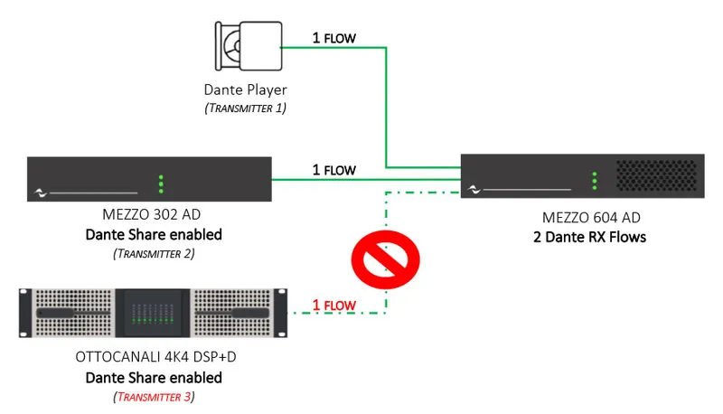
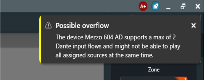
Figure 1 – Overflow Example scheme and Armonía PlusWarning
Dante input and output capabilities
The Dynamic Music Distribution capability of the system also enables dynamic routing. Dynamic routing enables the user to easily share their analogue or AES3 signal with other amplifiers on the network through DANTE receivers. This is made possible with the use of DANTE transmitters available on select Powersoft amplifiers.
Some considerations need to be kept in mind on the number of simultaneous DANTE sources that one amplifier can convert vs. the number of simultaneous DANTE sources that one amplifier can receive. This is due to the Dante flows available related to the number used within the amplifier.
The table below shows the type of DANTE chip being deployed in each Powersoft amplifier and the number of DANTE inputs / outputs and DANTE flows available.
AMPLIFIER SERIES DANTE CARD DANTE Input DANTE Output DANTE Flows TX DANTE Flows RX
X Series Brooklyn II 16 8 32 32
T Series Ultimo XT 4 4 2 2
MEZZO AD Ultimo XT 4 4 2 2
Ottocanali DSP+D Brooklyn II 16 8 32 32
Quattrocanali DSP+D Ultimo XT 4 - - 2
Duecanali DSP+D Ultimo XT 2 - - 2
Table 2 – List of Dante-enabled Powersoft amplifiers.
Notes:
One Unicast Dante flow (configuration by default) can contain up to 4 audio channels while One Multicast Dante flow can contain up to 8 audio channels.
Dante " transmit " flows are used when sending audio out from a Dante device and a " receive " flow is used to accept audio in from another Dante device.
Zoning capabilities
Dynamic Music Distribution enables the system to differentiate zones assigned to one or more amplifiers without needing a central DSP or zone mixer. Do take note that the number of zones that an amplifier can have does not always correspond to the number of outputs available on the amplifier.
Here is a list of the various amplifiers and their zoning capability.
AMPLIFIER SERIES MAXIMUM ZONES AVAILABLE
X8 4 Zones
X4 2 Zones
T Series 4 Channels 2 Zones
T Series 2 Channels 1 Zone
MEZZO A/AD 2 Channels 2 Zones
MEZZO A/AD 4 Channels 4 Zones
Ottocanali DSP+D 4 Zones
Quattrocanali DSP+D 2 Zones
Duecanali DSP+D 1 Zone
Table 1 – Maximum zones available on Powersoft amplifiers.
Notes:
As a rule of thumb, except for MEZZO Series, all other amplifiers have ½ the number of zoning capabilities compared to their outputs.
Dynamic Music Distribution does not support speakers linked in “ Spit Mode” to amplifiers, so they cannot be assigned to any zone.
What is Dynamic Music Distribution?
Dynamic Music Distribution offers System Integrators the ability to scale inputs and zones conveniently and efficiently with dynamic routing capabilities embedded in its amplifier platforms. This makes it simpler to share music between different zones independently from the source location and to carry control signals in an automated fashion without the need for a centralized DSP.
MEZZO Series
2 questionsHow can I monitor Powersoft Amplifier?
If using DMD, the user can use HealthPlus.
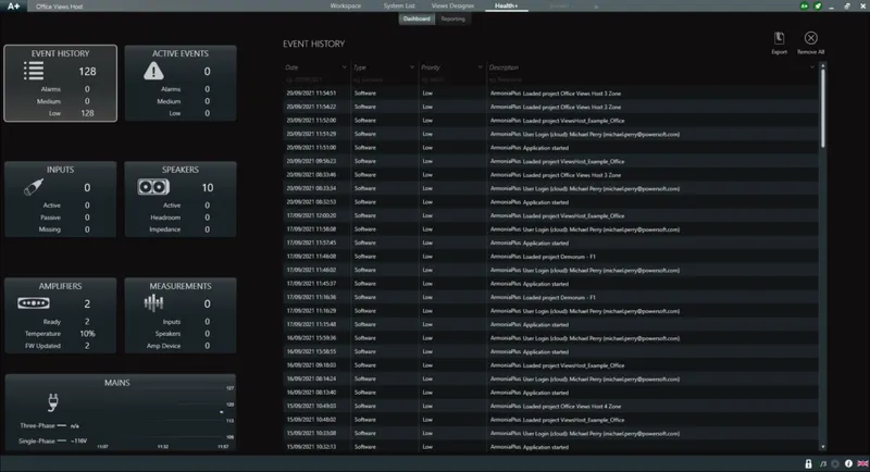
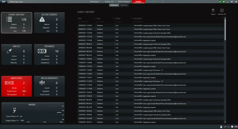
If not using DMD the user can monitor the MEZZO with the 3rd Party API, HealthPlus, or SNMP.
What is the max number of zones supported by Mezzo?
Maximum number of zones depends on the model that you have. See the Application Note - Dynamic Music Distribution Design Guide
Solutions
4 questionsVideo analysis on Deva HD
Deva HD model is equipped with a Full HD camera that provides ONFIV-compliant video streams. Those streams are available on the entire local network through any rstp media player, so Deva HD can easily be integrated with third-party video-analysis software to manage the different scenarios, improving the security:
- Video surveillance
- Abandoned object detection
- Queue evaluation(People counter)
- Parking Control
- Gate transit(People counter)
- Restricted area intrusion detection
- Social distancing(Crowding monitoring)
The scenario listed above can be set using the provided video-analysis software V-Track for Win10 OS or Reko for Ubuntu OS and require a compatible graphic card with memory resources, based on the number of video flows that need to be processed.
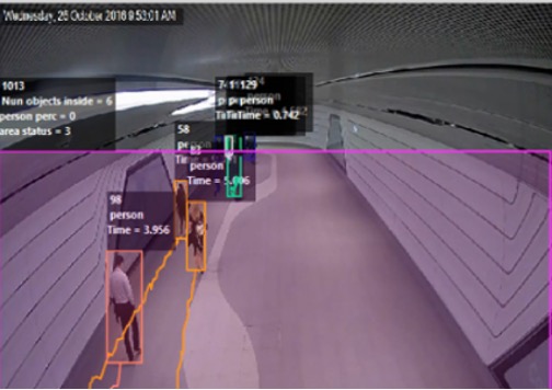
Figure 1 – Example of Queue evaluation.
Notes:V-Track and Reco are external software that requires additional licenses per video flow.
Requirements Chart
Understanding the key elements and the requirements needed, when designing a solution for infotainment and security with Deva Audio / Deva HD, is the primary aspect to achieve the best result from the entire system. The following chart describes the compatible and suggested options based on specific solutions.Solutions
Model
Mains Options
PoE Injector Power Supply Solar PanelHigh Schools and Education(Background Music)DEVA Audio P P
Zoos and privately owned public parks(Scheduled Messages Playback)DEVA Audio P P
Smart City Plans(SOS Emergency)DEVA HD P PCollege-University dorm areas(Video Analysis)DEVA HD P P Table – Deva Solutions Requirements Chart - Main Options.Solutions
Model
Connectivity Options
Network Cable WiFi Mobile SIMHigh Schools and Education(Background Music)DEVA Audio P PZoos and privately owned public parks(Scheduled Messages Playback)DEVA Audio P PSmart City Plans(SOS Emergency)DEVA HD P
College-University dorm areas(Video Analysis)DEVA HD P Table – Deva Solutions Requirements Chart - Connectivity Options.Solutions
Model
Features Available
Full HD Camera LEDs Light Motion Sensor VoIP -SIPHigh Schools and Education(Background Music)DEVA AudioZoos and privately owned public parks(Scheduled Messages Playback)DEVA AudioSmart City Plans(SOS Emergency)DEVA HD P P P
College-University dorm areas(Video Analysis)DEVA HD P P P
Table – Deva Solutions Requirements Chart - Features Available. P Suggested for best performances
In addition to the suggested option
Additional License required
Models: Deva HD, Deva Audio, Deva Passive
Deva HD and Deva Audio offer a versatile system of Mains powering and Network connectivity allowing a perfect integration to the central infrastructure. Deva HD and Deva Audio provide a link to connect a Deva Passive device for expanding the audio coverage area.
Mains options *:
External PoE injector (Solar Panel may be added on request)
External Power Supply (Solar Panel may be added on request)
Solar Panel (In addition to PoE or to PowerSupply )
Connectivity options:
Network cable (Cat5e or higher)
WiFi connected to an existing AP (signal above -56dBm and Star topology required)
Mobile SIM Card (Used for Voice Calls on SOS Box or SMS Alert)
Management System:
PDD (PC running DSM software on Ubuntu 18.04 LTS)
Deva System Manager (Remote control software with web-based user interface)
Gigabit Network Interface Card (Connected to Deva network)
External Soundcard (suggested to use “Live from Mic” feature)
Video-Analysis platform ( V-Track for Win10 OS or Reco for Ubuntu OS)
Dedicated GPU supporting Compute Unified Device Architecture (Required if using Video-Analysis)
*Internal Battery (12V – 12Ah) is required
Deva solution requirements
As an advanced multimedia device, Deva is a convergence of multiple devices that can be easily deployed anywhere, enabling automated and direct interaction with the public. Its camera, high-powered speaker, and multiple sensors are designed to complement each other and interact with third-party applications to offer several services spanning from safety to information and entertainment.
This article describes optimal requirements when creating and setting up a complete Deva Infrastructure for Infotainment and Security solutions. There are many different considerations that need to be evaluated when designing a Deva Solution, so, as best practice, is always suggested to be supported by our Solution Engineering Team to be sure the system can be created having the right requirements and fulfill all customer needs.
WM Touch
24 questionsWhat PoE Standard does the WM Touch adhere to?
IEEE 802.3af-2003 PoE standard provides up to 15.4 W power on each port. It uses a minumum of 44vDC.
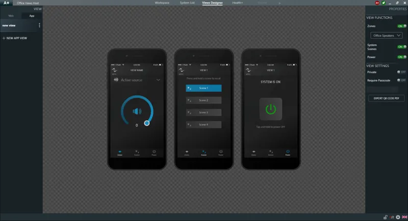
The GUI layout of controls for WM Touch and Sys Control App is predefined and fixed, but the integrator can pick and choose which parameters to control?
True. The graphics once selected, their position size and color are fixed. However not all controls need be present. Bselecting the check boxes for the parameters in the WM Touch, or by turning on the switches in the Views Designer the programmer can add the desired control parameters to the control scheme.
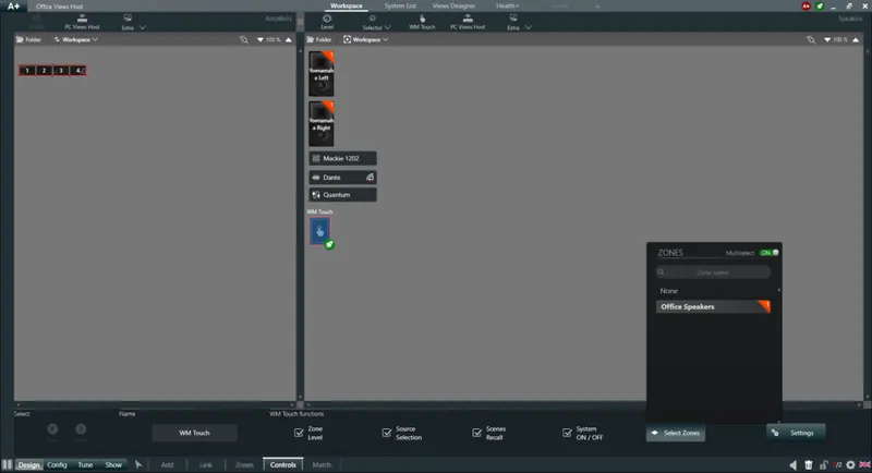
Can we make multiple channels from multiple amps work as a single zone?
Yes. Any channel from any amplifier can be the member of a zone, but a member of only (1) zone. Amplifier channels can not be members of multiple Zones. Once an amplifier channel is assigned to a zone, it can no longer be assigned to be a part of any other zone.
Can I use a WM touch as part of a typical network and use standard network switches, Category cable and PoE?
Yes, the WM touch is a PoE network device and can be incoorperated in any standard network. The WM Touch is powered by standard PoE and can be connected with Category 5 or higher unsheilded cable.
Can I use the WM Touch and passive WMP Controllers in the same system?
Yes, however, all controls assigned to the passive controllers will be read-only in the WM Touch. In other words, if the level of a zone is controlled with a local WMP knob, it will not be possible to control this level from the WM Touch.
My WM Touch is displaying an "Update Fail" message. What should I do?
It is likely that the device firmware needs to be updated. Please check the Troubleshooting section in the product's User Guide for detailed instructions regarding the upgrade of firmware in the WM Touch.
What is the maximum cable length for Category cable recommended for use on a network supporting the WM Touch?
A maximum lenght of 100 m (328 ft.) is recommended.
What type of Ethernet cable should I use to conenct the WM Touch to the network?
Category 5 or higher grade cable.
Can I configure the IP address of the WM Touch to be static?
Yes. The IP Address can be configured to be static in Armonía Plus. This parameter is found under Config > IP.
Does the WM Touch use standard PoE, PoE+, or PoE++?
Standard PoE. The IEEE 802.3af-2003 PoE standard provides up to 15.4 W power on each port.
Can the WM Touch operate in either Landscape or Portrait Mode?
Yes. This can be set from the Hidden Settings menu in the WM Touch. Check the product's User Guide section Local Configuration for more information.
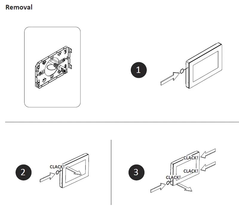
How do I remove the WM Touch from the wall?
Using the removal pin provided with the product, unclip the panel from the metal plate. Be very careful not to damage the Touchpanel. The metal plate is hooded onto integrated plastic tabs of the WMT Touch. The Tool is used to unhook the metal hooks from the plastic tabs.
What mounting options do I have for the WM Touch?
Use a standard (1) Gang Electrical box. Low Voltage boxes are acceptable. The box should be mounted horizontally to support the Landscape orientation. The electircal box should be mounted vertically to support the Lortrait orientation.
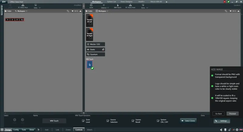
Can I apply a custom logo to the lock screen of the WM touch ?
Yes, a custom image can be loaded from Armonía Plus. You must use a 100 pixel X 100 pixel .png graphics file.
Can I customise the layout of the WM Touch?
No. The layout uses fixed graphics with designated positions of appearance. Much time and thought went into the User Interface Engineering and Control System flow. This feature adds value as the integrator does not have to spend time creating custom graphics themes for the customer.
Can the WM Touch be combined with 3rd party control plug ins like Crestron?
Yes, the commands for changing sources and zones can be generated by 3rd party control devices
Do I need to keep Armonía Plus running when the WM Touch is controlling the system?
No, there is no need for any computer connected to the system when WM Touch is running in the system.
How do I need to configure WM Touch
Some configurations such as screen orientation and language can be set directly on the device. More advanced configurations will require Armonía Plus. Please refer to the product's Users Guide here for more information.
Is it possible to combine the WM Touch with the Sys Control App or Web Views in the same system?
Yes, the WM Touch includes the Views Host for running controls on the Sys Control App and Web Views, so no additional hardware is needed
Can I use multiple WM Touch panels in a system?
Yes, there is no restriction to the number of WM Touch panels used in a system
Which Powersoft products can be controlled with the WM touch?
MEZZO is the perfect fit for WM Touch, however any DSP+Dante enable Powersoft product can be controlled
Can I restrict access to the WM Touch controls?
Yes, a screen unlocks passcode can be set.
Do I need the Views Host running on a PC if I have a WM Touch in my system?
No, the WM Touch has an embedded Views Host and can also be used to run the Sys Control App and Web Views
What am I able to control with the WM Touch?
Input source selection per zone
Level and mute per zone
Scene Recall
System Power On/Off
Speaker Presets
4 questionsBasic concepts and operations of the limiters
The main purpose of this article is to provide a better understanding of how to use the different types of limiters available in Powersoft amplifiers. This document is applicable to the following product lines: X Series, T Series, Otto / Quattro /Due Canali DSP+D series, MEZZO Series, and Loto DSP.
Choosing the correct limiter is not an easy task and many aspects need to be considered, e.g.: it can be difficult to decide thresholds and time constants to obtain the correct balance between protection and sound quality, hence every decision should be based on a wider knowledge of the component to limit. Limiting may be considered an “art” and many different approaches and philosophies can be followed. For this reason, this guideline intends to simply provide a starting point on limiter parameters and how to handle them with Powersoft devices.
NOTE: Powersoft is not responsible for misuse of the information contained in this document and/or any potential loudspeaker or other damages derived from incorrect limiter settings. This article serves as a general guideline and is subject to the context in which it is applied.
Are Presets for Canali Series compatible with the MEZZO Series?
MEZZO's DSP is different from Canali series DSP, although a lot of presets are compatible. Adding a speaker in Armonía Plus you can filter the list of speaker selecting the voice "MEZZO Compatible"
Can I link the speakers to the M and K Series amplifiers?
Unfortunately, this function is only present on the X Series, Canali DSP+D Series and MEZZO Series. This because of the difference in the DSP.
Can I load an M-Series preset in the K-Series and vice versa?
For the M and K series, there are some differences in the DSP that involves the compatibility of the presets. If you need to copy a preset for the M Series on the K Series, you should copy filter by filter manually. In addition, there are additional features on the K Series that are not present on the M Series. For more information, you can use Armonía Plus to add offline amplifiers to understand the differences.
Products Info
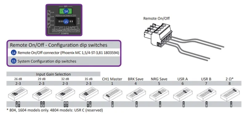
9 questionsHow to set the energy save on the Canali Series?
To activate the Energy Save mode on the Canali Series, the DIP Switches on the rear panel for Duecanali and Quattrocanali and on the front panel for Ottocanali Series must be used. The activation times are 4 seconds for Ottocanali and 30 Minutes for Duecanali and Quattrocanali Series. Through Armonía Plus you can change the activation time and the threshold for the input signal that will activate the energy save.
How to change the brightness of the T-Series display?
In the display go to page 10, hold the "cogwheel" key for 3 seconds and then choose the "LCD brightness" option. You can choose between: Dark, Normal, Bright.
How can I change or reset IP address of my M Series amplifier?
Use Lantronix Device Installer and follow our Tech Note: M series IP Management and Recovery
The amplifier is showing a Red light what do I have to do?
X Series Red Light means a hardware fault. Reboot the amplifier and if the red light is still present contact Powers Service Center at service@powersoft.it
How to make the auto setup in the MEZZO Series?
Just hold down the button in the rear panel for 3 seconds, the amplifier will send a signal to the speakers, it will make specific measurements and settings for each channel and after a few seconds the amplifier will be ready for use. Autosetup also can be triggered from Armonía Plus under "Autosetup" Tab in the workspace.
Can I use Mezzo with both Hi-Z and Low-Z loudspeaker?
Yes, the amplifier is capable to work in mixed configuration without any problem. To protect loudspeaker be sure to have the right preset loaded or use the AutoSetup function.
Can I control the volume of the amplifier with an external potentiometer?
Yes, MEZZO Series and Canali series (except for Ottocanali) amplifiers have a dedicated VCA input where a 10kOhms potentiometer can be connected.
Can I save the settings (snapshot) of an X Series amplifier on the K Series?
Unfortunately not because they have different DSPs, to better understand these differences you can use Armonía Plus, adding the amplifiers in offline to understand what each DSP offers you.
How can I export Log files in X Series amplifiers?
Insert USB Key (FAT32) in the front panel an press together CH2 & CH3 buttons (on X4 / X4L) or CH 4 & CH 5 (on X8)
Network setting
7 questionsHow to reset the network in the T Series?
In the display go to page 9.1, hold down the "cogwheel button" for 3 seconds and then confirm the operation that will reset the network and report the amplifier to DHCP. If you want to also reset Dante Network of the amplifier just go to the next page 9.2 and do the same operation.
Is it possible to have control redundancy via Armonía Plus?
Unfortunately it is not possible to have the redundancy in the control but only the redundancy of Dante, in the X and Ottocanali Series.
How to reset the network in the Canali Series?
Remove front panel left mask (magnetic) and press the soft reset button for 3 sec.

How to reset the network in the X Series?
Press together Wi-Fi button and Callback Button until front panels leds start flashing green. Release the buttons and wait the amplifier reboot itself.
I can't discover my amplifier in Armonía Plus
Enable the network card in the communication manager of A+. If the problem persist do a network reset of the device.
How to update the K Series firmware?
To update the K Series firmware, you must contact the distributor or Service Center nearest you. Specifying the model, and current amplifier firmware.
Do I need to connect the amplifier to a DHCP server to control it?
No, DHCP server is not required. If you don't have a DHCP server the amplifier will automatically take the IP address 169.254.xxx.xxx.
Firmware updates
3 questionsHow to update the K-series firmware?
To update the K Series firmware, you must contact the distributor or Service Center nearest you. Specifying the model, and current amplifier firmware.
I want to update my amplifier's firmware manually. Where can I find the firmware to download?
All firmware can be found on our website: https://www.powersoft.com/en/download/firmware/
How to update my amplifier with the latest firmware available?
Go in the System List page is it possible to update firmware for T Series, X Series, Canali Series and MEZZO Series.
Amplifier Platfotms
1 questionLimiter Type: Rms, Peak, And Clip
To avoidmechanicalandtemperature-relateddamagestwo kinds oflimiterscan be used:
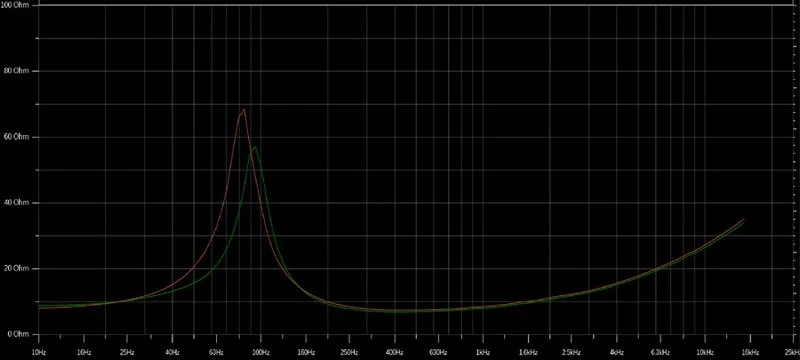
- RMS limiter:Protectsspeakersagainst thermal damage whenexcessivepoweris applied for extended periods of time, resulting inoverheating, and eventuallyburning. Designers should be aware of the maximum long-term power safely applicable to speakers (AES power rating). An interesting approach to RMS limiting is one that uses coil temperature control looking at how the peak in the impedance curve changes when the speaker starts heating.
Infigure 3we can see the relationship between the temperature and impedance curves: the green curve is the curve measured when the speaker is at 26°C, meaning it is cold. The orange curve is when the temperature increases to 38°C. We can notice that when the speaker starts heating up the impedance peak will become higher in value and will shift slightly in frequency. Therefore, being able to monitor the impedance changes in real-time will allow us to save our loudspeaker. Complete knowledge of the driver’s limits allows for keeping the temperature level in a safe interval not only to avoid damage.
Live impedance curves
- Peak and limiter: Protect against mechanical damages. Designers should set these limiter parameters as a function of both the maximum displacement (XMAX) of the diaphragm and the speaker's maximumtoleratedvoltage.
NOTE: Relying on peak limiting only for speaker protection can still lead to excessive long-term average power and consequential damages.
Dante/AES67
3 questionsAre Powersoft amplifiers compatible with Dante Domain Manager?
All Powersoft amplifiers that have the latest Dante firmware can be enrolled in a Dante Domain
Are Powersoft amplifiers compatible with AES67?
All Powersoft amplifiers with the lastest Dante firmware support AES67
How to update the Dante firmware?
Using Dante Updater integrated into Dante Controller. All firmwares can be also found on our website: https://www.powersoft.com/en/download/firmware/
Armonía Plus
41 questionsHow to control a system via VPN
To enable this control, we need first go under options, and choose the tab VPN.
Now we need to insert the static IP address of every device we desire to control, in this example 10.10.1.1, click on enter e then click on apply.
Now we can discover our device in the match function.
And this is how you can easily control a device through a VPN.
How to update the amplifier firmware
To update, we must go to Design, Match, and then click on Discovery.
We will see all the devices in our network, and below we will see the number of amplifiers that have new firmware available.
By clicking here ... we would go directly to the System list view, where we could see the current firmware version in red and the new version available.
We can select one or more amplifiers simply by holding down 'shift', then we click on the 'Update' button, and then again on the 'Update' button.
Once the upgrade is complete (which may take a few minutes) you can check the version of the firmware installed.
Returning to Workspace, you will see that the amplifiers will be ready for use.
Synchronization, Controls & Views
A new feature added to Armonía Plus is the Synchronization button. It can be accessed by clicking on the upper right ‘A+’ emblem and is available from any window within the software in both the Live Sound and Install skin of Armonía Plus.
This feature allows the user to freely design using online amplifiers without making real-time changes within the current project while Synchronization is off (shown in red). While Synchronization is off the user cannot add any discovered amplifiers to their project and any amplifier previously synched to the project will appear offline.
When Synchronization is enabled Armonía Plus will pull all amplifier data in real-time to the active project. Here you can see we have enabled Synchronization and the emblem is now green. If the user would like to match virtual amplifiers to the discovered amplifiers the Synchronization feature must also be turned on.
To the right of Synchronization is the newly added Controls and Views button (rocket button). When the button is disabled, the user has full control of the system via Armonía Plus and no passive controls or views will be useable. Once engaged the user can control the system with the use of passive controllers and Views. Light control within Armonía Plus is allowed but only consists of EQ, Mute, Polarity, and Level changes.
Some Error messages may occur when trying to run the Controls and Views. It is important to note that these error messages are not bugs within the software but are due to one or many instances and it is recommended to check that all Zones, Sources, Speakers, and Amplifiers have been assigned properly within your project.
When enabling ‘Run Controls and Views’ Armonía Plus will let the user know that they are about to deploy an active system and will prompt the user to save the current setup before deployment. Once the project has been saved the system will configure itself to ‘Run’.
Once complete, a window with a checklist will appear confirming which ‘Views Host’ the system is running, that audio settings have been loaded to the amplifiers, and that the user can now close Armonía Plus. This can also be confirmed by viewing the status of the ‘green’ colored rocket found in the upper right-hand window.
With the proper use of Synchronization, Controls, and Views, the designer can be assured their system is complete and ready for deployment, allowing the end user, smooth, precise control of their background music system.
Project properties
In this section, we will look at how an Armonía Plus project designer can use the project properties section on Armonía Plus to enable project details, Views Host, and access support information of the said project.
Within the Workspace select the A+ emblem found in the upper left-hand corner of the program window and click ‘Project Properties.’
This is the ‘Project Properties’ section. This section is divided into 3 subsections.
We are currently looking at ‘Project Details’ sub-section. This is where the designer can input information about this project such as ‘title’, ‘address’, and notes about the project. Let's input the information about this project.
Next, let’s select Views Host. Within this sub-section, the designer can control the currently active View Host by selecting the Views Host within the ‘preferred’ column. Here they can also view the ‘location’ of different Views Host within their project. Lastly, they can choose whether to exclude certain Views Host’s from their project by clicking the ‘No Symbol’ found in the ‘Actions’ column.
Now, let's access the ‘support’ sub-section. This is where the designer can input the support details for this project so that when the need arises, the client can conveniently access the details in the ‘Sys Control App’. Information such as the person in charge, ‘name’, ‘company’, ‘email address, and ‘phone number' can be inserted here. Let’s input the information for this sub-section.
After all the information has been keyed in, we can now deploy this project to our system.
Now let’s move to Sys Control App.
While in the Sys Control App, if the client would like to gain access to the support information, all they need to do is to select the “i” icon on the top right corner within the ‘Control System’ page of the application.
The Project Properties tab is a very useful window to address certain aspects of the project file. It not only allows the designer a preferred choice over the Views Host server but also gives the end user quick access to technical support information if the need should arise.
Hotkeys Armonía Plus
F1 Workspace E+4 Gain
F2 System List E+5 Shading
F3 Operator View E+6 Delay
F4 Health+ E+7 Polarity
A Amplifiers E+8 EQ
S Speakers E+9 Headroom
D Dual View R+1 Mute (Show)
< Arrow R+2 Gain (Show)
Q Design R+3 EQ (Show)
W Config R+4 Mains (Show)
E Tune R+5 Impedance
R Show R+6 Headroom (Show)
Q+1 Add Ctrl+Scrool Zoom
Q+2 Link Ctrl+A Select All (Amplifier or speakers)
Q+3 Match Ctrl+C Copy (Amps, speakers and others)
W+1 IP Ctrl+V Paste (Amps, speakers and others)
W+2 Preset Delete Delete (Amps, speakers and others)
W+3 AutoSetup Ctrl+Shift+V Pack Vertical
W+4 Input Ctrl+Shift+H Pack Horizontal
W+5 Matrix Ctrl+Alt+V Orientation Vertical
W+6 Damping Ctrl+Alt+H Orientation Horizontal
W+7 Mains Cmd/Win+N New Project
E+1 Mute Cmd/Win+S Save
E+2 TestSys Cmd/Win+Q Exit
E+3 Solo Cmd/Win+M Minimaze
Accessing the View Host device
Once theControl Viewsare tested the user can close Armonía Plus. Using the IP Address given by the ‘View host device’ (Figure 11), any PC or mobile device connected to the network can now access and control the availableWeb ViewsandApp Views(Figure 12).
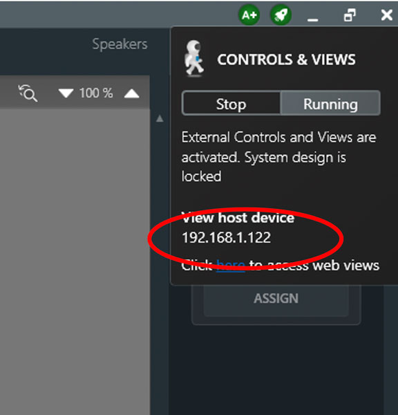
Figure 11 - Views Host IP Address
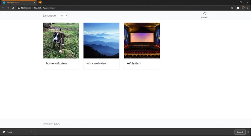
Figure 12- Views Host Device Web Views
Additional Notes The IP address provided under ‘View host device’ inFigure 11above is the IP Address of the computer which is currently managing the control of theWeb Views.Views Host software needs to be installed on a computer permanent to the network subnet as the Powersoft system in order for theViewsto be accessible. This is not necessary if using the WM Touch, because the Views Host lives on the device. If we use the example created inFigure 11above, ‘View host device’ tells us that the IP Address to access theWeb Viewsis at IP Address: 192.168.1.122. If the user wants to deploy a WM Touch as the ‘View host device’they simply would use the IP Address of the WM Touch to access anyWeb ViewsorApp Views.
Running Controls and Views
Once the user has completed designing the necessaryWeb Views,App Viewsand/or configuring theWM Touch,the system is ready to be launched (Figure 8). In the upper right corner of Armonía Plus, click on the rocket to open theControls & ViewsTab. After selectingRun, if not saved, Armonía Plus will present a window prompting the user to save the project file (Figure 9). Once the initialization of theControls & Viewsbegins, the user will notice theHealthPlusTab illuminating red and showing an alarm status (Figure 10). This is an expected operation and will clear onceControls & Viewsare running.
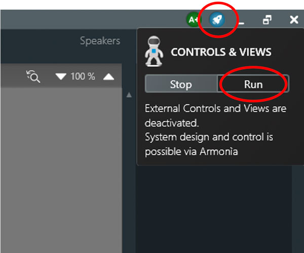
Figure 8 - Running Controls and Views
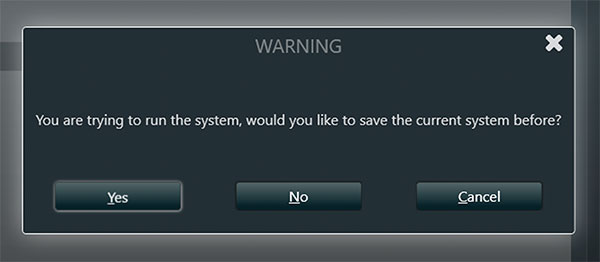
Figure 9 – Prompt to Save File Before Running

Figure 10 - HealthPlus Briefly Illuminates Red when Controls and Views begin toRun
Discovery and synchronization
After completing your design within Armonía Plus, selectDesign>Match>Discovery, found in theWorkspace,and turn onSynchronization(Figure 6). Match the corresponding amplifiers within the tray to the virtual amplifiers in theWorkspace. ForSynchronizationto complete leave theMatchtab. TheDesynchronization Window(Read/Send Dialogue) will appear once leaving theMatchtab and selectSend(Figure 7). WhenSynchronizationis complete the amplifier will appear online within theWorkspace.
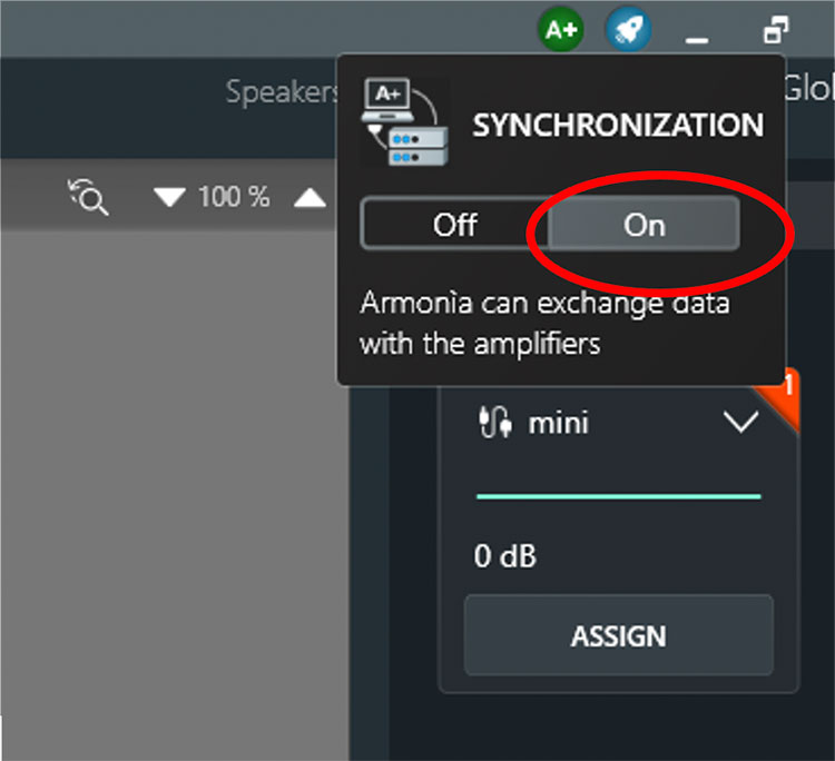
Figure 6 – Discovery and Synchronization
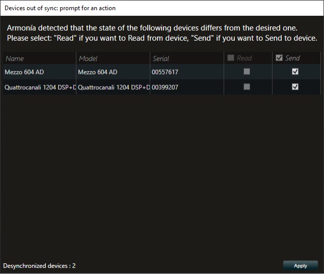
Figure 7 - Desynchronization Window
WM Touch network recovery
Thanks to the release of Armonía Plus 2.2 network recovery of the WM Touch is now possible.
Installers can now easily discover and configure the IP Address of a WM Touch from a different subnet. Users can configure the IP Address of the WM Touch by right-clicking on the devices found within Match.
Making the WM Touch network recovery easily accessible gives installers and users a quick and reliable way to manage their devices on the network.
WM Touch
When installing the WM Touch within a project it is important to note that the Views Host is already integrated within the device and no external computer is required to run Views Host (Figure 4). The user may also control the system using theControl Sys ApporWeb Viewscreated in Armonía Plus. This is possible because the WM Touch is also the active Views Host device. A wireless router connected to the same network subnet as the WM Touch is required (Figure 5).
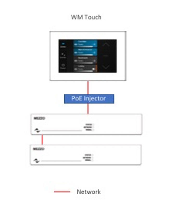
Figure 4- WM Touch Views Host Example
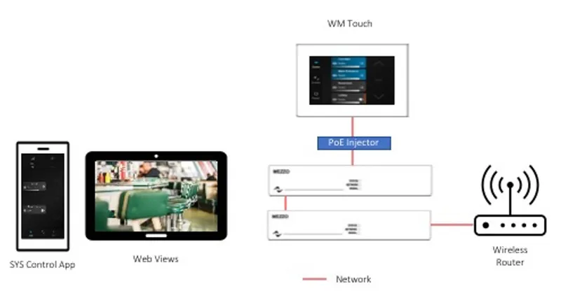
Figure 5- WM Touch Views Host with Sys Control App and Web Views Example
OS and network operation for Views Host
The Views Host can be installed onto a computer utilizing a Windows 10 x64 Operating System (OS). The system requirements are minimal. The computer should have 2GB of RAM and 100MB of drive memory available. Once installed the application can be found running in the Window’s Task Manager on theDetailsTab asViewsHost.exeandViewsHostService.exe(Figure 2). Views Host can be installed on multiple machines across the same network subnet. This allows the integrator to install Views Host on their own PC as well as a permanent PC that will live with the Powersoft system. When the project is complete, the integrator can remove their computer from the system and leave the management ofWeb ViewsandApp Viewsto the remaining permanent Views Host PC on the network (Figure 3). This allows the end user to have access toWeb ViewsandApp Viewsfor control, but not the entire Armonía Plus configuration file.

Figure 2- Views Host Running in Windows Task Manager
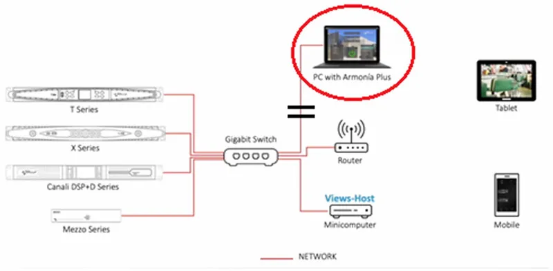
Figure 3- Views Host Network Example
IMPORTANT NOTE: If there are multiple Windows-based computers operating the Views Host on the same network, the PC which has received or has been assigned the lowest numbered IP Address will be given control of the system unless defined within Armonía Plus.
How to install the Views Host
To install the Views Host software, click the following link:Armonía Plusand scroll to the “Armonía Plus downloads” section of this web page. Within this section, one will find Views Host software available (Figure 1). Click on the link and follow the installer’s prompts.
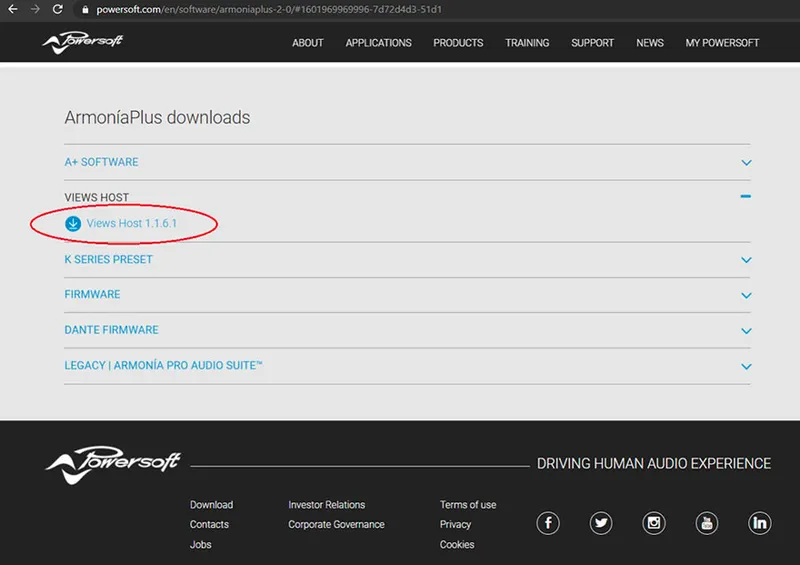
Figure 1- Views Host Download Link
IMPORTANT NOTE: If the integrator chooses only passive controls such as the Powersoft WMP LEVEL and WMP SELECT in the Armonía Plus install project, there is no need to install Views Host software. Views Host software is only needed if the integrator plans to deployWeb Viewsand/orApp Views.
Views Host
Installing and running the Views Host software is an essential step in providing the end-user with access to the pre-designed Web Views and App Views of an Armonía Plus Install Project.
The Views Host application installs a Windows Service called “ PowersoftViewsHostService ” which runs automatically at Windows startup. The Windows Service needs to be installed and to operate on a Personal Computer (PC) that resides on the same network subnet as the Powersoft system.
Views Host software contains the control engine required for the deployment of Web Views or App Views control. Web Views control can be accessed with any web-browser and App Views control can operate on a mobile device using the Powersoft app SYS CONTROL. Within this document we will discuss the necessary steps for a successful installation of Views Host software onto a PC.
Can I receive the list of Alarms by email?
Ineventsreportingyou can enable various Users toreceiveanemailreportsent by HealthPlus everyhour. You can choose thelanguagein which to receive the report, whether to receive the events of a specificproject, orglobalof any project loaded, and also choose whether to receive only thealarms, the alarms +mediumevents, alarms + medium andlowevents.
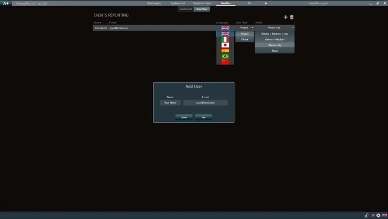
Events Reporting
For HealthPlus to work itrequiresa computer with Armonía Plus running and an activeinternetconnection.
Below you can see an example of HealthPlus email reporting.
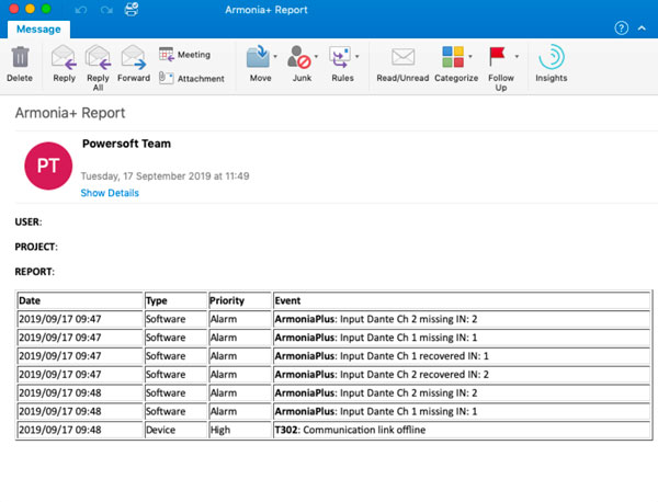
Email Reporting
Can I view a list of Alarms?
In Event History, we can see the date of the event, type of event: Device or Software, priority: low, medium or alarm, and the description of the event. We can also export them to a file (.xlsx), and remove them all.
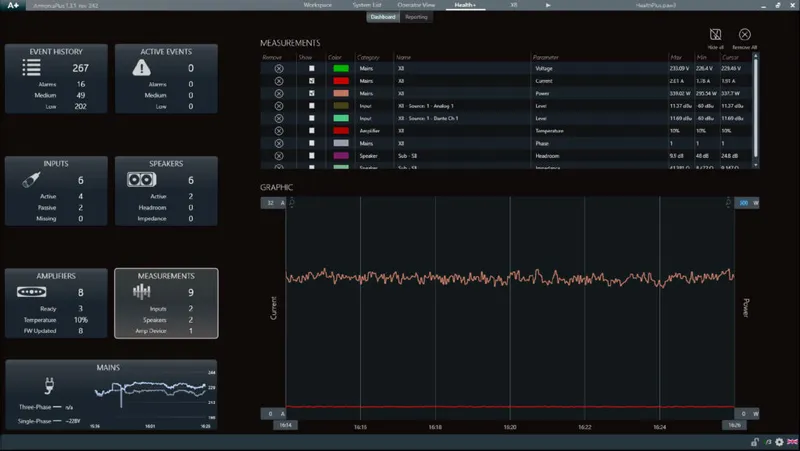
Event History
Active EventsIn "Active Events" we can see the events and alarms that are happening in the system. Also, we can see the example of a loss in audio channels, we see exactly how many channels were lost, which input format, amplifier, and channel, so that we can be precise in solving the problem.
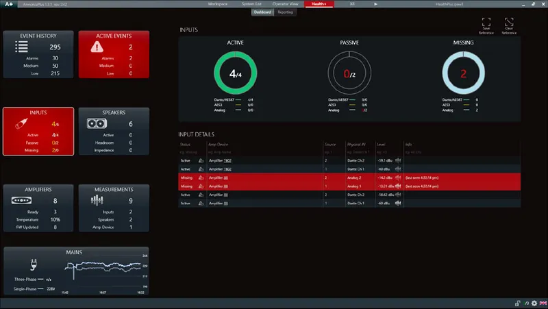
Active Events
What can I measure with HealthPlus? Mains
We can measure: Phases, Voltage, Current, and Power. (Figure below)
Measurements: Current and Power.
Hide and remove all
HealthPlus can have a maximum of 10 measurements enabled and display a maximum of 2 different ranges at a time, it’s possible to hide the measurements and delete all.
The saved measurements refer to the last hour of use.
What can I measure with HealthPlus? Amplifiers
We can measure the Temperature.
What can I measure with HealthPlus? Outputs
We can measure theHeadroomandImpedanceof thespeakers. (Figure below)
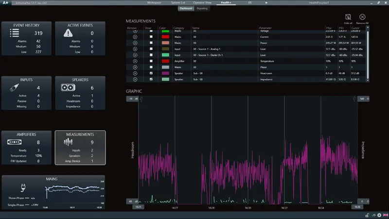
Measurements Speakers: Headroom and Impedance.
What can I measure with HealthPlus? Inputs
In HealthPlus we can measure variousdatapoints of a system. These measurements can be input channels, data related to thespeakers,and measurements that concern the mains. To select a measurement, click on the measurement icon.
The columns present in the measurements are:
- Remove and Show
- Color: This allows you to change the color of the measurement.
- Category, Name, and Parameter
- Max and Min: it indicates the maximum and minimum value of that particular measurement.
- Cursor: It shows you the value of where the mouse is positioned.
Inputs We can measure the input level in all formats,Dante / AES67,AES3(Digital), andAnalog. (Figure below)
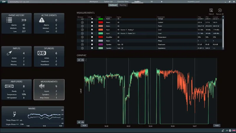
Measurements Inputs: Dante and Analog in Backup Strategy.
What can i monitor with Healthplus? Mains
Mains In this section it is possible to monitor the mains of the amplifiers. (Figure 5)
- Status
- Rack Name: The rack where they are positioned on theworkspace.
- Amp device: Their name.
- Amp model (Serial): The amplifier model andserialnumber.
- Phase
- Voltage
- Current
- Power
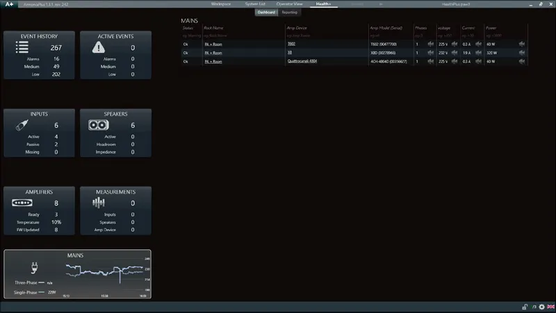
Figure 5 - Mains
StatusThe status of the amplifier in‘Mains’tab can be:
- Ok
- Virtual
- Offline: when we lose theconnectionwith an amplifier or when we turn it off.
- Warning(Phase): when there is a phase loss.
- Warning(Voltage): when an amplifier deviates from theaverage.
What can i monitor with Healthplus? Amplifiers
Amplifiers In this section, it is possible to monitor the status of the amplifiers by name, model, serial number,temperature, andfirmware. (Figure 4)ReadyIn the ready category, we can monitor amplifiersonline,stand-by,andoffline.TEMPERATUREEach amplifier model has different temperature ranges where they can work, also different points inside the amplifier where the temperature is taken to bemonitored, and to simplify readings to the end customer we have opted for a new way of viewing this inpercentage.
- 0% - 100%: Is an optimal range for working.
- 100% – 150%:Limitsthe outputs to reduceheatand helpcooling.
- > 150%: The amplifier could turn off to protect itself.
Firmware In Firmware we can monitor the total number of amplifiers:
- Updated: That has the latest firmware available.
- Outdated: amplifiers that have a more recentfirmwareavailable forupgrade.
- Not supported
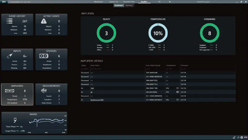
Figure 4 - Amplifiers
StatusThe status of the amplifier in the ‘Amplifiers’ tab can be:
- Ok
- Virtual
- Discovered: An amplifier seen indiscovery, but which has not been added to the workspace.
- Stand-by
- Outdated: Amplifiers that have a more recent firmware available for upgrade.
- Not Supported
- OverTemp: >150%
What can i monitor with Healthplus? Speakers
Speakers In this section, it is possible to monitor the status of the speakers, which amplifier they are connected to, which output they are connected to, ways description, overall output gain, headroom, and impedance of the speaker. (Figure 3)
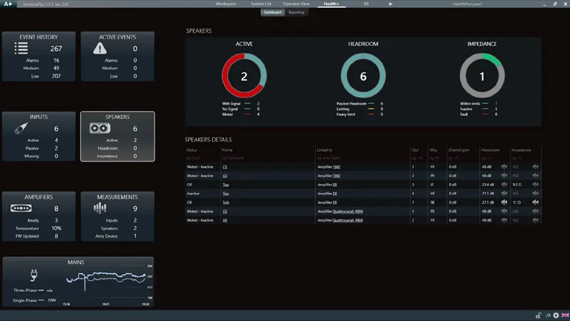
Figure 3 - Speakers
ActiveIn active, we can monitor the speakerwith signal,no signal(without signal), andMuted.HeadroomIn headroom, we could monitor:
- Positive Headroom:This means that you still have headroom to increase the volume in case you need it.
- Limiting:You have reached the limit of the loudspeaker! We recommend do not increase the volume more, if you need more SPL increase the number of speakers or select a more powerful loudspeaker.
- Heavy Limit: It means that the channels are limiting more than 12 dB ofgainreduction.(This could be because you have an under-sized system, increase the number of loudspeakers, or select a more powerful loudspeaker.)
ImpedanceIn this section, it is possible to monitor the speakers working within the nominalthresholdrange, which are inactive, and the loudspeakers at fault.
- Within the range: It is based on the impedance entered in the speaker preset information (.spk3). If no value is entered, the result is always within the nominal range.
- Inactive: When the amplifier is not reading the impedance, it will show the last measurement made.
- Fault: When the measurement is out of the established nominal threshold range.
E.g., with an 8 Ω speaker, the upper limit is 4x (32 Ω) and the lower limit is 1/2 (4 Ω), so above 32 Ω and below 4 Ω, HealthPlus will send an alarm Fault. TheHi-Zdescription appears in the X and Ottocanali Series above 400 Ω, and the T Series, Duecanali, and Quattrocanali above 100 Ω.
What can i monitor with Healthplus? Inputs
Inputs In this section it is possible to monitor the inputs channels, their quantity in total and are divided intoActive,PassiveandMissingcategories. (Figure 1)
Active
These are the inputs that are playing, independent of the format. We can monitor the total number of input channels for:
- Dante / AES67
- AES3(Digital)
- Analog
Furthermore, in status, there is the possibility to ignore one or more channels so that HealthPlus does not always signal an alarm. e.g., when youmutethe mixer master or between tracks using a media player.

Passive
These are the signals present in thebackupstrategy, ready to become active as needed.
e.g., For input redundancy, when we lose a digital input and have an analog signal in the backup strategy.
Missing
Signals are lost since you saved the reference.
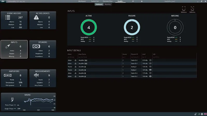
Figure 1 - Inputs
Save & clear reference
With HealthPlus it is possible to monitor the number of input signals and you can also save a reference so that Armonía Plus sends you analarmwhen this reference changes. By clicking on save the reference, (4/4), which would be the number of channels present / the number of reference channels.
E.g., when you lose one or more input channels. A recommended time to activate this reference is at the end of a soundcheck or at the end of an installation. (Figure 2)
Figure 2 - Save and clear reference
What is Healthplus?
Is the new Armonía Plusmonitoringandmeasurementsystem, which allows you to accurately monitor each amplifier, speaker, and in-and-out signals. Furthermore, you allow yourself to measure a lot of information for analysis.
HealthPlus, replaces the software’s previous ‘Events’tab, giving sound engineers and integrators a streamlined monitoring environment of all elements in a given sound system with improved communication, control, and reporting ensuring even better performance than ever before. HealthPlus updated display gives engineers a complete suite of system diagnostic controls to monitor the health and effectiveness of any sound system in real-time, it can be used with a touring PA or in fixed installations like cinemas, airports, theme parks, etc. In addition to input monitoring for power amplifiers, speakers, and other connected devices, the system is also capable of measuring system health indicators such as headroom, temperature, voltage, and impedance to ensure optimal performance of all elements and will automatically alert users in case of malfunctions or element failures. Engineers can also now utilize the Event History function to track uploaded programs, and user logins, and diagnose any long-term system issues. Finally, HealthPlus has improved reporting, giving users the ability to track multiple indicators at once over an hour time log period for more detailed system monitoring.
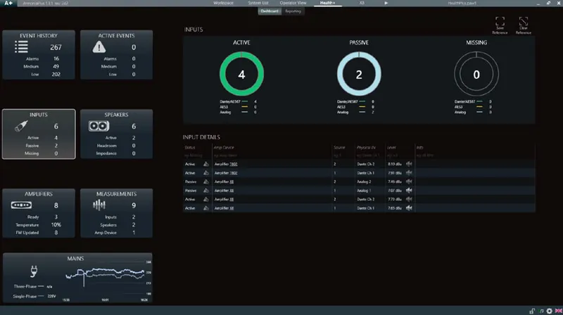
App View
The ‘ Views Designer’ tab can be accessed across the top portion of the Armonía Plus 2.0 Workspace window or by pressing F3 on your keyboard. Within this tab you will find the App View tab, which is located on the left-hand side of the Views Designer window.
To add a new App View simply select “New App View”. You have the option to Delete, Rename or Duplicate the current App View.
To the right-hand side of the Views Designer Window, we can access the App View Properties menu. Within the View Functions we have the option to engage Zones, System Scenes, and Global Power On/Off. Shown in our App View Screen we can select multiple or independent Zones while controlling Levels, Sources, and Mutes.
By enabling our System Scenes, we have the ability to recall scenes with just the press of a single button. Turning on Power gives us full global control of our amplifiers by simply pressing and holding the button for a few seconds.
Lastly, we have the option of engaging this App View to be private and whether it will require a password for control access. We can also generate the QR code of this App View to share with other Users.
What data can you see in the System List?
The System List displays the main details of all the amplifiers making up the current Setup (either on-line or off-line). The System List is a useful tool both in live events and in maintenance environments, where multiple units have to be monitored.
HEADER ROW
The view is completely customizable: it is possible to select what column to show or hide. Right click on the header row and select among the following:
Dante Name
Load Imp. W
Mains limit
Preset list revision (only for Loto)
Model
Preset ( Snapshot. pam )
On/Off
MAC Address
Mains
Scheduler
Routing Adjustments
The ability to change between a mono, stereo or summed send within the installation skin of Armonía Plus is quick. The software allows the user simple manipulation of their systems routing with just the click of a mouse. Within this video we will explain how to adjust the routing assignments within a project while referencing an existing example named ‘Install One’.
To access the routing assignments within Armonía Plus we need to select the ‘Config’ > ‘Routing’ tab found across the bottom portion of the Workspace. Within this tab, we will find the ‘Source Format’: Mono, Stereo, and Multi-Channel. By selecting mono and choosing our ‘Zone 2’ loudspeakers we can choose if this group of loudspeakers is ‘ ON’, this will allow the source to send. we also have the option of whether it is ‘ OFF’, this mutes the send.
Let’s now select ‘Stereo’ within the ‘Source Format’ tray below. Choosing ‘Stereo’ and clicking on our point source loudspeaker within ‘Zone 1’ we can change the loudspeaker from a ‘Left’, ‘Right’ or ‘Summed Left and Right’ send. You can notice that ‘Zone 1’ is configured as a ‘Stereo’ send with both ‘Left’ and ‘Right’ sends selected within this zone. ‘Zone 2’ and ‘Zone 3’ have been selected as a ‘Summed Left and Right’ send. We also have the option to turn these sends ‘OFF’ just like was shown within the ‘Mono’ ‘Source Format’.
Choosing ‘Multi Ch.’ within the ‘Source Format’ tray will allow the user to choose multiple channels for individual loudspeakers. This routing option can be used for surround sound systems and will support a Dolby Atoms system of sixty-four channels when used in conjunction with a Dolby Atmos processor.
Armonía Plus is here to help the user's installation move quickly and efficiently. Routing within Armonía Plus is simple and intuitive, allowing the user confidence, knowing their system is rooted for success.
Mono-Mix Source Dante Sharing
Armonía Plus 2.3 now features Mono-Mix Source Dante Sharing. This new feature addresses the use of Powersoft’s Dynamic Music Distribution system. It enables users to have more stereo sources available in designs when using 4-channel MEZZO AD models while driving 2 or more zones.
The ability to distribute a stereo source as a Mono-Mix on Dante gives value to a system. Users can now save Dante input channels on receiving amplifiers, allowing them to have unique stereo source selections available for each zone. This benefit allows for example the use of a single MEZZO 604AD to drive for independent zones, each playing different background music sources.
The use of this feature only applies to system designs using MEZZO AD models. The Mono-Mix Dante sharing capabilities are limited to sources that are physically patched to MEZZO AD analog inputs and shared over Dante.
To add a Mono-Mix Source within Armonía Plus simply choose Design > Add and select ‘Source’ found within the upper window of the loudspeaker workspace; With the source in the workspace select it and choose ‘Analog’ as the format. Next, select ‘ Mono ( L+R mix )’ in the dropdown window. Now, choose ‘ edit patch’ and patch left and right to inputs 1 and 2, and enable Dante sharing.
Armonía Plus 2.3 now gives the user more stereo sources in designs when driving 2 or more zones using 4-channel MEZZO AD’s. Another example of Powersoft’s technologies supporting its ever-growing user base.
Does Armonía Plus have an Autosave function?
Yes. Autosave can be managed from 'Options' (A+), 'General' and by configuring the parameters under the Autosave option. The "Open Autosave Folder" button is used to recall saved files. You can also access the autosave files by clicking the A+ logo and selecting "New/Open"
How to save a Template?
Just create your project and then go to A + menu and choose Save as template. Each time you open Armonía Plus you will have the option to start from the previously created project.
How many groups can be assigned to a speaker?
Up to a 8 Advanced/Array groups.
How many filters can I set in the advanced/array groups ?
Up to 32 filters per layer, 3 layers for each EQ, for a total of 96 filters per channel.
How can I reset my Powersoft Amplifier?
Add your device into the workspace, right-click on the amplifier, then select Device-->Reset
Where can I find plugins for OEM manufacturers?
In Market Place, (which is in the A + menu) where you can install the plug-ins already present there as well as the preset libraries that each brand makes available. If you can't find the plug-in you want on Market Place, get in touch with specific brand support and they will support you.
What is Health +?
Is the new Armonía Plus monitoring and measurement system, which allows you to accurately monitor each amplifier, speakers, and in-and-out signals. Furthermore you allow yourself to measure a lot of information for analysis.
Where are the Armonía Plus events, can't I find them anymore?
Events has been replaced with the new monitoring and measurement system called Health +. Health_ can be accessed from the top middle section of Armonía Plus.
How can I open an Armonía Plus project automatically whenever I turn on my computer?
Just copy a link of the project to this directory: C:\Users\admin\AppData\Roaming\Microsoft\Windows\Start Menu\Programs\Startup
Can I add custom images to my Speaker presets?
Yes, with the new .spk3, you can add your custom images as well as add MEQs and enter useful data for the final customer. Further information can be found inside the DSP of an amplifier such as the X Series on the part: Speaker configuration.
I cannot patch my Dante input from Armonía Plus, what is missing?
First, make sure you have Armonía Plus V1.4 and above for this feature. To be able to patch your amplifier's Dante input from Armonía Plus, select the "A+" logo, go to "Options", on "Options", select "Communication Manager". On "Communication Manager", select the "Dante" column for the network poert you are working with. Bear in mind if Dante is enabled for the port, Armonía Plus would be enabled as well. To disable Armonía Plus for the said port, click the radio button to turn it "OFF".
What is MEQ "Manufacturer EQ"?
MEQ are a set of equalizations that the manufacturer develops for a speaker or a series of speakers to compensate low frequencies (Speakers coupling) to compensate the air loss (Long, medium, short throw) and for Low / High Contourn equalization or for musical styles.
Is there a Mac OS version of Armonía Plus
At the moment Armonía Plus is only for Windows platform but can be used on Mac OS running a Virtual Machine software like "Parallels" or similar. The application note on how to do this is available here
Amp Modules
20 questionsCan you indicate me how many 3004PFC4 amplifiers can be connected in daisy chain through PowerCON?
Using Line @ 16A
N° 4 @ 230V N° 2 @ 115V
Using Line @ 32A
N° 8 @ 230V N° 4 @ 115V
How can i download the ProManager licence for the access?
You can download your license directly from the “OEM Manufacturer Registration” page.
- Go to the OEM Manufacturer Registration page following this link http://armoniaproman.powersoft.it/
- Log in using your account and password
- You’ll see your data and, if the Powersoft staff has confirmed your registration, it will be possible to download your license. So, click the button in order to start the download.
- Since you have got the license, copy it in the folder that you can find following this path C:\Powersfot\Armonía ProManager\Settings\Licence
- Try again to open ProManager, it should open without any request.
What might be the consequences in terms of limiter settings, if a manufacturer were to establish an input/output gain, selecting a DigiMod 38 dB with the 32 dB jumper in place? How do they work the scale factors for DSP-4?
When you choose a wrong amp model as connected (so, for example, DigiMod 1000 rather DigiMod 2000HV) the different scale factors provide a wrong meters measurements and a wrong limiters behavior.
These scale factors are: current scale factor for the current reading, voltage scale factor for the voltage reading, output scale factor to obtain a gain consistent with the amplifier gain response, temperature scale factor for the temperature reading and finally, “output capacitor value” for the improving of the current reading (in some amplifiers, there is an output capacitor that makes difficult the current reading, so setting this scale factor we can give a virtual capacitor that removes the capacitor value that pollutes the reading)
The last setting regards the “active channel”. This one is used to make compatible the IpalMod and M-Drive with DSP-4, because they have only one output channel, without this selection the DSP-4 “sees” the IpalMod and M-Drive always in protection state.
In this case, if you select DigiMod 3004 38dB for a DigiMod 3004 32dB (really connected), the only difference will be the gain response: DSP-4 applies +6dB in input to the amplifier and so with a sine signal @ 1Vrms in input, the voltage and current response will be different than uses a right gain setting selected. Anyway, the limiter should work well because the other scale factors are the same for both type of amp module, so it will be like increasing the DSP-4 input sensitivity.
How can I modify the D-Cell504 flat cable in order to connect two XLR connectors for each channel?
Following the schematic you can do what you need. Anyway is strictly recommended to use this kind of cable only for the amp evaluation.
We used 32bit OS and therefore the 32bit Sigma Studio. I’ve changed my operating system to 64bit and the 64bit Sigma Studio software works, but it can’t read the “old” 32bit setups. Why isn’t it possible?
The preset templates that you build with a x86 release of SigmaStudio, are not compatible with X64 release because the instructions set is different. We recommend using one system dedicated to the programming with 32bit O.S., stable and functioning. You don’t need a powerful PC for the DSP programming, for example with the last O.S. or with the best processor, but is important that you have a system that never stops.
How can I balance the DSP outputs ch3-ch4?
It’ possible to do a balancing circuit using one NE5532D for each output channel. If you would like to manage the outputs independently, you could add a potentiometer before the 10Kohm resistor. Following this circuit, we’ll have a good balancing with low distortion level (not measurable) and the best S/N ratio.
Is there a way to monitor the load impedance connected on DigiMod?
The only way to monitor the load impedance on DigiMod is using Armonía Software, you will need of a converter UART/RS485 called ProNet485 that allows doing the remote managing.
D-Cell504 has the Load Impedance Measurable that would give the possibility of monitoring each separate channel. Is this feature applicable in Bridge Mode also? If yes, which are the connector pins to use?
There aren’t pins that allow the load impedance monitoring for the speakers connected in bridge mode, but you can get the singles values for each channel and summing these it will obtain a single one, doing so you will get the load impedance in bridge mode.
Is DSP mounted in a DigiMod IS different by the DSP provided in the D-Cell504 DSP IS? Is it possible to exchange them?
The DSP-C and DSP-D are external boards mounted on DigiMod IS or provided with the integration kit, in the D-Cell504 DSP, this one resides within. You can’t use the DSP-C/DSP-D even for D-Cell.
What do they mean the led on control-board plus of DigiMod Series?
Left side / right side: there are two yellow LEDs indicate the signal presence.
Top center (going from left to right): there are 5 leds indicate respectively:
Protection: Led is lit becoming red when the protection is activated in the output 1 (for example when the output is in short circuit)
The presence of +5, this is a green led, it’s normally lit when the module is on.
The presence of +12, this is a green led, it’s normally lit when the module is on
The presence of -12, this is a green led, it’s normally lit when the module is on.
Protection: Led is lit becoming red when the protection is activated in the output 2
Can I put in parallel both outputs of the D-Cell504 without problems in order to rise lower minimum loudspeaker impedance to 2 Ohms?
This is a not recommended practice that increases the damage risk. The two output channels of amp module are not equal perfectly (one is inverted respect the other) and the signal in output, even if the input signal is the same for each amp module, will be processed differently. In our amps modules the minimum load impedance is always 4ohm and not is possibile to have a lower load impedance.
What do they mean the led on mainboard of DigiMod 3000 PFC?
Top-left side: there are three green LEDs (except the one in the middle, that is yellow). They indicate respectively (from left to right):
The presence of +18, this led is normally lit when the module is on.
If the Energy Save mode is on, this led is normally lit when the module is on (Energy Save is enabled as default).
The presence of +VCC
These leds must be normally lit when the module is on.
Top-right side: there are three green LEDs indicate respectively (from left to right):
The presence of -VCC,
The presence of +7VDC
The presence of -18
These leds must be normally lit when the module is on.
Bottom left side: there is one yellow LED that is lit when the fan is activated
In D-Cell504 4ch module the fan in the center doesn’t work even if board is hot, is that normal?
Yes, it’s a normal behavior because the fan starts to run when the module temperature is approximately 60°. It’s strange only if the module exceeds this value and the fan doesn’t start. Anyway, the module goes in thermal protection when the temperature value exceeds approximately 75° reducing the signal output.
How can I set the DigiMod in order to use it @ 110V?
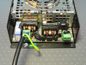
See the picture and follow these steps:
- Insert the jumper in the phoenix 2 poles connector called F1 (that is in the right side of the amplifier).
- Connect the mains (120v) in the phoenix connector CN1 (in the left side of the amplifier)
I would like to replace the DigiMod’s fan, what is its NPN?
DigiMod mounts an ADDA fan with wiring included, manufactured by our supplier. You can buy the fan only without wiring and so connect the molex following the pin-out like the original fan.
Search NPN: AD0824UB-D90(T)
Regarding DigiMod 3000 PFC, What is the current consumption for the 2 units working together?
∼7,6A @ 115V
∼4A @ 130V
∼4A @ 230V
I have an amp module set at 230Vac. As soon as I turn it, supplying 230Vac, the fan starts to run for few seconds. If I leave the amp module, set at 230Vac supplying it with 125Vac, the fan starts to run at low speed, without stop itself. Is there an explanation?
When DigiMod is turned on, fan starts to run for few seconds, then the fan will start to run again only after that the limit threshold temperature will be exceeded and so the fan will provide to cool the amplifier. When you supply 230Vac in a DigiMod set at 230Vac, the fan’s behavior is normal as described in the question. Instead, if you supply 125Vac in DigiMod set at 230Vac, the module’s power supply tries to start all process, but the voltage is lower than those needed. In this case, the microprocessor attempts to start himself (so does run the fan), then due to the absorption caused by the starting attempt, DigiMod reaches the voltage value that triggers the protection called “undervoltage”. This behavior becomes a sort of loop because the amp module attempts to start working but it fails, so it tries again and again. For this reason, the fan seems to move constantly, but this is due to its mechanical inertia.
How should I connect the signal input to D-Cell504, without input interface, if I would like to use it in Mono input configuration?
If you use D-Cell504 in Mono Input configuration, you must connect the input to channel 1 and channel 2 in parallel following these instructions:
1) Connect the input signal to input channel 2 in CN1 connector:
N2- to PIN4
N2+ to PIN5
GND to PIN6
2) Connect the input channel 2 in parallel with input channel 1 in the same CN1 connector:
PIN5 to PIN22
PIN4 to PIN23
PIN6 to PIN21
BY1 in/out and BY2 in/out are the pins of input and output to connect an external potentiometer to control the input channel or even to add something like an analog HP Filter or pad attenuator. If you don’t want to add any kind of processing in input, please connect together these pins:
PIN7 to PIN8
PIN19 to PIN20
How should I connect the micro-match connectors from the input interface to the DSP-D/C board?
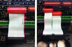
The pictures here below, explain how to connect the micro-match connectors. You can take as reference the type of socket to decide how to pose the micro-match: one flat cable has two micro-match connectors for a total of 26 poles, the other one has only a 20 poles micro-match connector. Please make attention to the red wire in the flat cables, this is used to define what is the first pin.
What is the difference between Lite and Pro Programming Board?
Lite Programming board allows you to store one preset at time with SigmaStudio connected by USB port. It’s needed to have a “link compile download” command and then press the store button to save the preset just compiled, in the preset slot selected by the amp module input interface.
Pro Programming board has been thought for the mass-production, in facts it allows you to store an entire bundle of 4 presets, obtained from a sort of “master loudspeaker”. As the Lite Programming Board, the Pro type allows you to store one preset at a time in the DSP of the loudspeaker that we’ll consider as the “master”; always using the PC to have a “link compile download” command by SigmaStudio. In addition than the capabilities in common with Lite Programming Board, the Pro type allows you to store inside its EEPROM memory, all 4 presets just stored in the “master” loudspeaker, in order to save this complete bundle in each loudspeaker that we want to initialize. This task is possible without any PC connection and supply (the amp module takes care to power the Pro Programming Board).
General
1 question4.7 Sites States
Sites can assume up to 7 states, revealing the health condition and the presence of active events:
OK:there are no active events and notifications are on.
LOW:there are “x” low-priority active events ongoing on the site
HIGH:there are “x” high-priority active events ongoing on the site
LOW & HIGH:there are “x” low-priority and “x” high-priority active events ongoing on the site
CRITICAL:the number of channels with at least one high-priority event, or belonging to a device with one high priortiy event or offline, is equal to or exceeds 50% of the total amount of channels of the site’s devices
OFFLINE:Every device is offline on the site
SILENCED:All notifications are turned off for the site