


Domande frequenti
Risposte su piattaforme di amplificazione, software e configurazione dei sistemi.
Configurazioni degli switch
6 domandeAbilitazione e configurazione dell’IGMP snooping
Per abilitare l’IGMP Snooping nello switch Cisco, quando serve traffico multicast:
Dalla pagina principale di configurazione dello switch, con il menu di sinistra, seguire il percorso ‘Multicast > Properties’ (Figura 12).
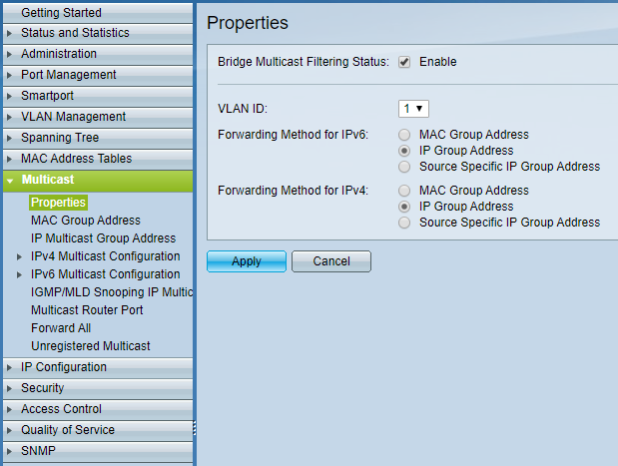
Figura 12 - Impostazione delle proprietà multicast.
Spuntare la casella di abilitazione di ‘Bridge Multicast Filtering Status’. In ‘VLAN ID’ selezionare la VLAN su cui verrà usato il traffico multicast. Se non è stata configurata nessuna VLAN, selezionare 1. SelezionareIP Group Addresssia per ‘Forwarding Method IPv6’ sia per ‘Forwarding Method IPv4’. Passare poi a ‘Multicast > IPv4 Multicast Configuration > IGMP Snooping’ (Figura 13).
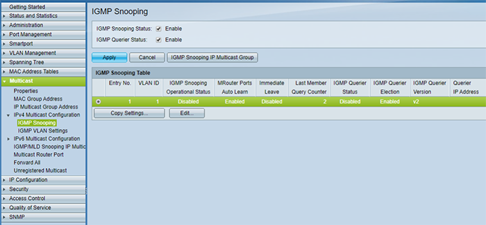
Figura 13 - Abilitazione dell’IGMP Snooping.
Spuntare la casella di abilitazione sia di ‘IGMP Snooping Status’ sia di ‘IGMP Querier Status’ e fare clic su ‘Apply’. Per modificare le impostazioni di IGMP Snooping, sempre nella stessa pagina, in ‘IGMP Snooping Table’ selezionare l’ID della VLAN multicast e fare clic su ‘Edit’. Si apre la finestra ‘Edit IGMP Snooping’ (Figura 14).
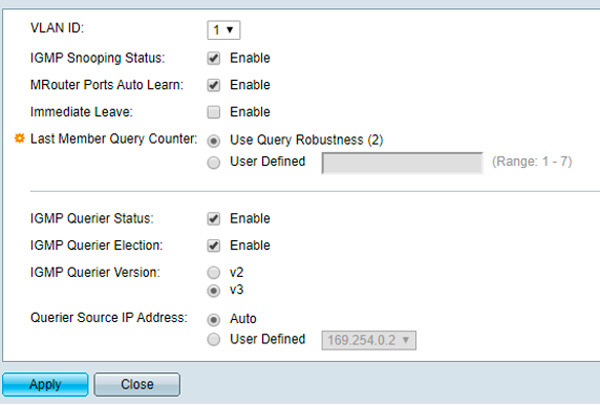
Figura 14 - Impostazioni di IGMP Snooping.
Verificare che ‘IGMP Snooping Status’ sia abilitato, come pure ‘MRouter Ports Auto Learn’. Abilitare poi ‘IGMP Querier Status’ e ‘IGMP Querier Election’, impostare ‘IGMP Querier Version’ suIGMPv3,e fare clic su ‘Apply’. È l’impostazione consigliata. Come già detto, Dante e AES67 supportano entrambi IGMPv2 e IGMPv3. L’importante è che tutti gli switch della rete siano configurati sulla stessa versione.NOTA IMPORTANTE:Come indicato nelle sezioni precedenti di questo documento, nelle reti con più switch è più sicuro tenere abilitato un solo IGMP Querier, preferibilmente su uno switch vicino alla radice della topologia di rete. In questo caso le funzioni del punto 9 vanno disabilitate su tutti gli switch a valle nella catena di collegamento che non devono funzionare da IGMP Querier.
Disabilitazione di Energy Efficient Ethernet (EEE)
Per disabilitare l’EEE nello switch Cisco:
Dalla pagina principale di configurazione dello switch, con il menu di sinistra, seguire il percorso ‘Port Management > Green Ethernet > Properties’ (Figura 11). Togliere la spunta alla casella di abilitazione ‘802.3 Energy Efficient Ethernet (EEE)’ e fare clic su ‘Apply’.
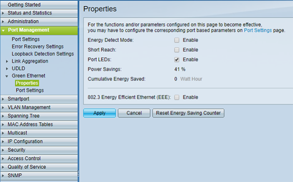
Figura 11 - Disabilitazione dell’EEE.
Configurazione DSCP per la gestione della QoS
Per configurare i parametri DSCP:
Dalla pagina principale di configurazione dello switch, con il menu di sinistra, seguire il percorso ‘Quality of Service > General > QoS Properties’ e abilitareQoS Advanced Mode(Figura 8).
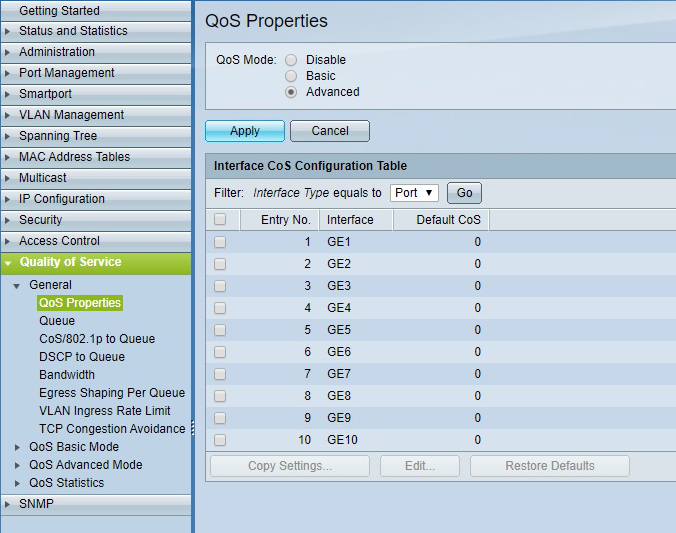
Figura 8 - Abilitazione di QoS Advanced Mode.
Occorre poi passare dalla gestione Layer 2 CoS alla gestione Layer 3 DSCP. In ‘Quality of Service > QoS Advanced Mode > Global Settings’ selezionareDSCPcome ‘Trust Mode’,Trustedcome ‘Default Mode Status’, e fare clic su ‘Apply’ (Figura 9).
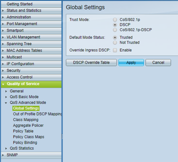
Figura 9 - Configurazione delle impostazioni globali.
Passare poi a ‘Quality of Service > General > DSCP to Queue’, indicare la coda di uscita prioritaria di ogni etichetta DSCP e fare clic su ‘Apply’ (Figura 10). Negli switch Cisco la coda numero 1 ha la priorità più bassa, la coda 4 la più alta. Le etichette a cui va assegnata una priorità dipendono dal tipo di rete audio in uso.
- Per Dante-AES67 (non Audinate)
- 56 (CS7) - 4 - 46 (EF) - 4
- 46 (EF) - 3 - 34 (AF41) - 3
- 8 (CS1) - 2 - - - 2
- Tutto il resto - 1 - Tutto il resto - 1
NOTA IMPORTANTE:Se la rete comprende altri sistemi preesistenti, per esempio una LAN VoIP, consultare l’amministratore di rete: le impostazioni sopra indicate potrebbero dover essere riviste.
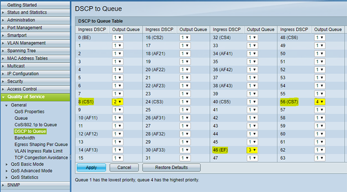
Figura 10 - Configurazione delle code DSCP.
Esempio di configurazione di uno switch di rete: Cisco sg300-10
Quello che segue è un esempio di configurazione di uno switch Cisco con alcuni dei parametri chiave per un corretto funzionamento Dante/AES67. Alla pagina di configurazione della maggior parte degli switch si accede digitando il suo indirizzo IP nella barra degli indirizzi di un browser. Perché funzioni, il computer deve trovarsi nello stesso range IP/sottorete dello switch a cui è collegato. Per impostazione predefinita gli switch Cisco sono nel range IP 192.168.1.X. Per cambiare indirizzo IP e subnet mask del computer, in WINDOWS:
- Collegare il computer a una qualsiasi delle porte ethernet dello switch.
- Su un PC Windows aprire la finestraEthernet Status(Figura 4). Di solito lo si fa dal ‘Network and Sharing Center’, facendo clic su ‘Ethernet’ fra le reti attive.
- Nella finestra Ethernet Status fare clic su ‘Properties’ per aprire la finestraEthernet Propertiese selezionare ‘Internet Protocol Version 4 (TCP/IPv4)’, poi fare clic su ‘Properties’ (Figura 5).
- Nella finestraTCP/IPv4 Propertiesselezionare ‘Use the following IP address’ per configurare un indirizzo IP statico per il PC (Figura 6).
- Digitare un indirizzo IP nella forma 192.168.1.X, dove X può essere un numero qualsiasi da 1 a 253, ammesso che nella stessa sottorete non ci siano altri dispositivi collegati allo switch a cui uno di quei numeri sia già stato assegnato.
In Subnet Mask digitare 255.255.255.0 e fare clic su ‘OK’.
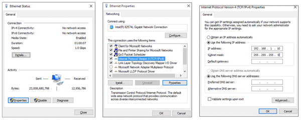
Figura 4 - Finestra Ethernet Status. Figura 5 - Ethernet Properties. Figura 6 - TCP/IPv4 Properties.
Terminata la configurazione dello switch, ricordarsi di ripristinare la situazione selezionando ‘Obtain an IP address automatically’ nella finestraTCP/IPv4 Propertiese facendo clic su OK. Una volta che il computer e lo switch di rete si trovano nello stesso range IP di sottorete:
Aprire un browser sul computer e digitare l’indirizzo IP dello switch nella barra degli indirizzi. Per impostazione predefinita gli switch Cisco usano l’indirizzo IP 192.168.1.254. Si apre così la pagina di configurazione dello switch (Figura 7). Digitare nome utente e password richiesti. Per l’SG350-10 il valore predefinito è “cisco” per entrambi i campi.
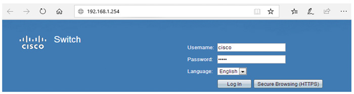
Figura 7 - Finestra Ethernet Status.
Una volta collegati allo switch ed effettuato l’accesso alla pagina di configurazione, è possibile raggiungere e regolare ciascuno dei parametri di configurazione.
Raccomandazioni per il traffico multicast
Le configurazioni di switch che seguono valgono per le reti con traffico dati multicast. I dispositivi Dante si possono configurare per trasmettere flussi audio unicast o multicast, mentre AES67 funziona solo con la trasmissione multicast. Con Dante il traffico dati unicast richiede meno configurazioni di switch e di routing e in condizioni normali è la soluzione più semplice e rapida per reti piccole e dedicate. In scenari più ampi, però, e soprattutto quando più dispositivi ricevono lo stesso flusso audio, per la trasmissione audio può convenire il multicast rispetto all’unicast. Se configurato correttamente, il multicast può essere più efficiente dell’unicast in termini di banda occupata. Per la massima efficienza e affidabilità del multicast si raccomanda che gli switch di rete abbiano:
IGMP Snooping attivo- Quando si usa traffico multicast è importante configurare la rete di conseguenza, per aumentare l’efficienza e ridurre la banda occupata. Senza una configurazione adeguata a gestire questo traffico, i pacchetti multicast vengono inviati in broadcast a tutti i riceventi del dominio, compresi i dispositivi che non li hanno richiesti (Figura 2). Per alcuni amplificatori questo può essere un problema, perché potrebbero non riuscire a gestire un numero elevato di pacchetti dati in ingresso. Per ovviare,IGMP Snoopingva attivato nello switch di rete. Internet Group Management Protocol (IGMP) è un protocollo di comunicazione usato per costituire i gruppi multicast e gestire l’appartenenza dei dispositivi che ricevono e trasmettono. All’avvio di una trasmissione multicast viene creato un gruppo multicast e viene inviato un annuncio a tutti i dispositivi della rete; i dispositivi che vogliono ricevere i pacchetti multicast inviano poi messaggi IGMP di join, indicando il gruppo IP multicast a cui vogliono aderire.IGMP Snoopingè il processo con cui lo switch di rete esamina le comunicazioni IGMP fra i dispositivi per costruire una tabella dei pacchetti multicast necessari e delle porte su cui servono. In questo processo lo switch inoltra i pacchetti dati multicast solo alle porte e ai riceventi designati (Figura 2).
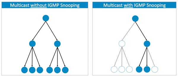
Figura 2 - Differenza fra la trasmissione dei pacchetti multicast con e senza IGMP Snooping attivo.
Ai fini di un funzionamento stabile dell’IGMP Snooping, anche unIGMP Snooping Querierdeve essere abilitato. Il querier serve a tenere aggiornata la tabella con tutte le appartenenze ai gruppi multicast. A intervalli regolari invia query IGMP a tutti i membri del gruppo IP multicast. Tutti i dispositivi che vogliono restare nel gruppo devono rispondere alla query con una conferma. I dispositivi che non rispondono entro un tempo stabilito vengono tolti dalla tabella del gruppo e non ricevono più quei flussi multicast. Una rete può ospitare più IGMP Snooping Querier (e ne sceglie uno automaticamente), ma è più sicuro tenerne abilitato uno solo, preferibilmente su uno switch vicino alla radice della topologia di rete. Alcuni switch permettono anche di configurare un ‘Query Interval’, legato al timeout di appartenenza al gruppo: è il numero di secondi che devono passare prima che lo switch stabilisca che nella rete non esistono più membri di un gruppo multicast. Con un ‘Query Interval’ ampio il tempo necessario perché il flusso multicast parta o si fermi si allunga e l’utente può notare che un amplificatore impiega più tempo a riprodurre l’audio. Più avanti in questo documento si trova un esempio di configurazione dell’IGMP Snooping per uno switch Cisco. Infine, IGMP ha tre versioni diverse: v1, v2 e v3. IGMPv2 supporta però IGMPv1 e IGMPv3 supporta IGMPv2. Anche se non tutte le funzioni di una versione precedente di IGMP sono supportate, quelle relative ai messaggi di membership query e membership report lo sono in tutte le versioni di IGMP. Per Dante e AES67 si raccomandano IGMPv2 o IGMPv3.Raccomandazioni finaliSeguono alcune raccomandazioni generali da tenere presenti, soprattutto nel caso di reti di grandi dimensioni:
Topologia- Il collegamento “daisy chain” può andare bene per mettere in rete i dispositivi, ma il guasto di un dispositivo della catena interrompe i collegamenti verso quelli più a valle nel “flusso”. In generale conviene pensare le reti a switch con una topologia a “stella”, o “hub and spoke”. In questo schema tutti i dispositivi di una stella sono collegati a un unico switch e, se un dispositivo si guasta, gli altri continuano a comunicare. Quando la rete cresce si possono aggiungere altri switch per estenderla. La topologia a stella si estende facilmente in una disposizione a stelle multiple, adatta a sistemi più grandi (Figura 3).
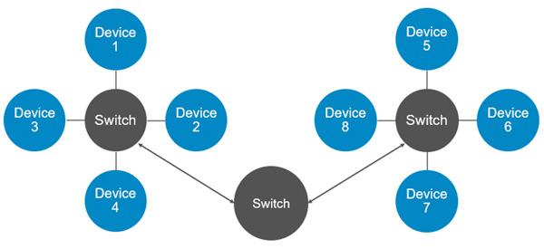
Figura 3 - Esempio di topologia a stelle multiple, in cui nessun dispositivo dista più di 4 “hop” da un altro.
Cablaggio- Per una rete Dante o AES67 va bene qualsiasi tipo di cavo ethernet, anche se in una rete a velocità gigabit si raccomandano cavi CAT5e o CAT6. I cavi CAT6 sono dati per una maggiore resistenza al rumore negli ambienti elettricamente rumorosi, ma per la maggior parte delle applicazioni il CAT5e è sufficiente. La lunghezza massima consentita per un normale cavo ethernet è di circa 100m. Per distanze maggiori serve la fibra ottica, che all’occorrenza può correre per diversi chilometri. Lo svantaggio è che i collegamenti in fibra richiedono interfacce di rete che li supportino, come le Small Form-Factor Pluggable (SFP).
Dante & AES67
Questo documento raccoglie raccomandazioni generali e configurazioni, con esempi, per gli switch di rete da usare con gli amplificatori Powersoft nella connettività Dante e AES67. Per il controllo e il monitoraggio remoto degli amplificatori è sufficiente qualsiasi switch di rete che lavori ad almeno 100 Mbps. Per il trasporto di audio over IP via Dante o AES67 possono invece servire switch e configurazioni dedicati, soprattutto nelle reti grandi e molto cariche o miste (per esempio audio più altri tipi di dati). Per la massima affidabilità di una rete Dante e/o AES67 si raccomanda che gli switch siano/abbiano:
- Adatti al Gigabit Ethernet- anche se per una rete piccola e dedicata all’audio 100Mbps possono bastare, le installazioni più grandi e più cariche possono richiedere uno switch che lavori ad almeno 1Gbps.
- Non-blocking- in questo tipo di dispositivo (oggi quasi tutti gli switch) tutte le porte possono lavorare alla massima velocità senza perdita di pacchetti dati. Lo switch regge la banda totale su tutte le porte e instrada verso qualsiasi porta di uscita libera senza interferire con il resto del traffico.
- Managed- a differenza degli switch unmanaged (plug-and-play), gli switch managed offrono una serie di opzioni e regolazioni, come la possibilità di dare priorità al trasporto di certi tipi di dati rispetto ad altri e di creare Virtual Local Area Network (VLAN), particolarmente importanti nelle reti miste dove l’audio convive con altri tipi di dati. Per reti piccole e dedicate all’audio gli switch unmanaged possono bastare per Dante e AES67. Nelle reti molto cariche, invece, o dove i flussi audio condividono la rete con altri dati (per esempio video, sicurezza, ecc.), è probabile che serva uno switch managed.
- Gestione della Quality of Service (QoS)- disponibile solo negli switch managed. La gestione di rete QoS permette allo switch di dare priorità a certi tipi di pacchetti dati rispetto ad altri. Questi pacchetti ricevono un trattamento preferenziale e vengono “spostati in testa alla fila” davanti al resto del traffico (Figura 1). Nel caso dei flussi audio la priorità va data prima ai clock per la sincronizzazione dei dispositivi e del segnale audio, poi ai pacchetti audio veri e propri. Serve a garantire flussi audio a bassa latenza e di alta qualità su tutta la rete. Le reti Dante richiedono almeno quattro code di priorità, AES67 solo tre.

Schema delle diverse code di priorità per la gestione dei dati audio in una rete AES67.
- QoS Differentiated Services Code Points (DSCP)- DSCP è un tipo di gestione QoS. Per dare priorità ai diversi pacchetti di informazione, le reti Dante/AES67 usano etichette e numeri DSCP per organizzare i pacchetti in code di priorità diverse. Questa gestione è compito dello switch: dove servono switch di rete managed, questi devono quindi lavorare con la QoS DSCP. Molti switch hanno attiva per impostazione predefinita la gestione Layer 2 “CoS QoS” e questa configurazione va cambiata in Layer 3 “DiffServ/DSCP QoS”. Una volta abilitata, controllare le assegnazioni di priorità. Lo switch richiede una configurazione specifica per riconoscere e dare priorità ai valori DSCP usati da Dante (Tabella 1) e da AES67 (Tabella 2). Più avanti in questo documento si trova un esempio di configurazione.
- CODE DI PRIORITÀ-USO-ETICHETTA DSCP-NUMERO DSCP
- 1. Alta - Sincronizzazione del clock - CS7 - 56
- 2. Media - Pacchetti audio - EF - 46
- 3. Bassa - (Riservata) - CS18 - 8
- 4. Nessuna - Altri pacchetti - Best-Effort - 0
Tabella 1 - Le diverse code di priorità di Dante e i rispettivi valori DSCP.
- CODE DI PRIORITÀ-USO-ETICHETTA DSCP-NUMERO DSCP
- 1. Alta - Sincronizzazione del clock - EF - 46
- 2. Media - Pacchetti audio - AF41 - 34
- 3. Nessuna - Altri pacchetti - Best-Effort - 0
Tabella 2 - Le diverse code di priorità di AES67 e i rispettivi valori DSCP.
Nelle reti miste con flussi Dante e AES67 generati da una scheda Dante si raccomanda di usare sempre i valori DSCP della Tabella 1 e di dare sempre la priorità più alta ai pacchetti di sincronizzazione del clock. I valori della Tabella 2 vanno usati solo nelle reti AES67 che non contengono flussi Dante.NOTA IMPORTANTE:Nei collegamenti su Wide Area Network (WAN) più estese, come quelle dei grandi ambienti aziendali, i tag DSCP possono non essere rispettati dai router di confine. Se il vincolo esiste, consultare l’amministratore di rete per valutare come aggirarlo.
- EEE (Energy Efficient Ethernet) DISABILITATO- gli switch che non hanno modalità di efficienza o di risparmio energetico non richiedono configurazioni aggiuntive. Negli switch che la offrono, però, questa funzione va disabilitata, perché impedisce il corretto funzionamento dell’audio over IP a bassa latenza: il risparmio energetico tende a ritardare i pacchetti inviati sulla rete. L’EEE viene talvolta chiamato anche ‘Green Ethernet’ o ‘IEEE 802’. Più avanti in questo documento si trova un esempio di disattivazione dell’EEE su uno switch Cisco. Attenzione: alcuni switch unmanaged hanno l’EEE abilitato per impostazione predefinita e non permettono di disattivare questa funzione.