


Domande frequenti
Risposte su piattaforme di amplificazione, software e configurazione dei sistemi.
Moduli di amplificazione
20 domandePotete indicarmi quanti amplificatori 3004PFC4 si possono collegare in daisy chain tramite PowerCON?
Con linea @ 16A
N° 4 @ 230V N° 2 @ 115V
Con linea @ 32A
N° 8 @ 230V N° 4 @ 115V
Come posso scaricare la licenza ProManager per l’accesso?
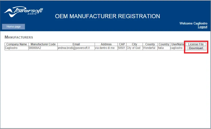
La licenza si scarica direttamente dalla pagina “OEM Manufacturer Registration”.
- Andare alla pagina OEM Manufacturer Registration seguendo questo link http://armoniaproman.powersoft.it/
- Accedere con il proprio account e la propria password
- Compaiono i propri dati e, se lo staff Powersoft ha confermato la registrazione, sarà possibile scaricare la licenza. A quel punto basta fare clic sul pulsante per avviare il download.
- Una volta ottenuta la licenza, copiarla nella cartella che si trova in questo percorso C:\Powersfot\Armonía ProManager\Settings\Licence
- Riprovare ad aprire ProManager: dovrebbe aprirsi senza richieste.
Quali conseguenze può avere sulle impostazioni del limiter il fatto che un costruttore stabilisca un gain di ingresso/uscita selezionando un DigiMod 38 dB con il jumper da 32 dB inserito? Come funzionano i fattori di scala per il DSP-4 Ω
Quando si sceglie come collegato un modello di amplificatore sbagliato (per esempio DigiMod 1000 invece di DigiMod 2000HV), i diversi fattori di scala portano a misure sbagliate dei meter e a un comportamento sbagliato dei limiter.
Questi fattori di scala sono: il fattore di scala di corrente per la lettura della corrente, il fattore di scala di tensione per la lettura della tensione, il fattore di scala di uscita per ottenere un gain coerente con la risposta di gain dell’amplificatore, il fattore di scala di temperatura per la lettura della temperatura e infine l'“output capacitor value” per migliorare la lettura della corrente (in alcuni amplificatori c’è un condensatore di uscita che rende difficile la lettura della corrente, quindi impostando questo fattore di scala si può dare un condensatore virtuale che elimina il valore di capacità che sporca la lettura)
L’ultima impostazione riguarda l'“active channel”. Serve a rendere compatibili IpalMod e M-Drive con il DSP-4, perché hanno un solo canale di uscita: senza questa selezione il DSP-4 “vede” IpalMod e M-Drive sempre in stato di protezione.
In questo caso, se si seleziona un DigiMod 3004 38dB per un DigiMod 3004 32dB (realmente collegato), l’unica differenza sarà la risposta di gain: il DSP-4 applica +6dB all’ingresso dell’amplificatore, quindi con un segnale sinusoidale @ 1Vrms in ingresso la risposta in tensione e corrente sarà diversa rispetto a quella che si ottiene con l’impostazione di gain giusta. In ogni caso il limiter dovrebbe funzionare bene, perché gli altri fattori di scala sono uguali per entrambi i tipi di modulo di amplificazione: sarà come aumentare la sensibilità di ingresso del DSP-4.
Come posso modificare il cavo flat del D-Cell504 per collegare due connettori XLR per ogni canale?
Seguendo lo schema si ottiene quello che serve. In ogni caso si raccomanda vivamente di usare questo tipo di cavo solo per la valutazione dell’amplificatore.
Usavamo un sistema operativo a 32bit e quindi Sigma Studio a 32bit. Ho cambiato il sistema operativo passando a 64bit e il software Sigma Studio a 64bit funziona, ma non riesce a leggere i setup “vecchi” a 32bit. Perché non è possibile?
I template di preset creati con una versione x86 di SigmaStudio non sono compatibili con la versione X64, perché il set di istruzioni è diverso. Si consiglia di usare un sistema dedicato alla programmazione con O.S. a 32bit, stabile e funzionante. Per la programmazione del DSP non serve un PC potente, per esempio con l’ultimo O.S. o con il processore migliore, ma è importante avere un sistema che non si ferma mai.
Come posso bilanciare le uscite DSP ch3-ch4?
È possibile realizzare un circuito di bilanciamento usando un NE5532D per ogni canale di uscita. Per gestire le uscite in modo indipendente si può aggiungere un potenziometro prima della resistenza da 10Kohm. Con questo circuito si ottiene un buon bilanciamento, con un basso livello di distorsione (non misurabile) e il miglior rapporto S/N.
C’è un modo per monitorare l’impedenza di carico collegata al DigiMod?
L’unico modo per monitorare l’impedenza di carico sul DigiMod è usare il software Armonía: serve un convertitore UART/RS485 chiamato ProNet485, che permette la gestione da remoto.
Il D-Cell504 ha la misura dell’impedenza di carico, che darebbe la possibilità di monitorare ogni singolo canale. Questa funzione vale anche in modalità bridge? Se sì, quali pin del connettore si usano?
Non ci sono pin che permettono di monitorare l’impedenza di carico dei diffusori collegati in modalità bridge, ma si possono prendere i singoli valori di ciascun canale e sommarli per ottenerne uno solo: così si ricava l’impedenza di carico in modalità bridge.
Il DSP montato in un DigiMod IS è diverso da quello fornito nel D-Cell504 DSP IS? Si possono scambiare?
Il DSP-C e il DSP-D sono schede esterne montate sul DigiMod IS o fornite con il kit di integrazione, mentre nel D-Cell504 DSP il DSP è interno. Il DSP-C/DSP-D non si può usare nemmeno per il D-Cell.
Che cosa indicano i led sulla control-board plus della Serie DigiMod?
Lato sinistro / lato destro: ci sono due LED gialli che indicano la presenza di segnale.
In alto al centro (da sinistra a destra): ci sono 5 led che indicano rispettivamente:
Protezione: il led si accende in rosso quando la protezione interviene sull’uscita 1 (per esempio quando l’uscita è in cortocircuito)
La presenza di +5: è un led verde, normalmente acceso quando il modulo è acceso.
La presenza di +12: è un led verde, normalmente acceso quando il modulo è acceso
La presenza di -12: è un led verde, normalmente acceso quando il modulo è acceso.
Protezione: il led si accende in rosso quando la protezione interviene sull’uscita 2
Posso mettere in parallelo entrambe le uscite del D-Cell504 senza problemi, per portare l’impedenza minima del diffusore a 2 Ohms?
È una pratica sconsigliata, che aumenta il rischio di danni. I due canali di uscita del modulo di amplificazione non sono perfettamente uguali (uno è invertito rispetto all’altro) e il segnale in uscita, anche se il segnale di ingresso è lo stesso per ogni modulo, viene elaborato in modo diverso. Nei nostri moduli di amplificazione l’impedenza minima di carico è sempre 4ohm e non è possibile avere un’impedenza di carico più bassa.
Che cosa indicano i led sulla mainboard del DigiMod 3000 PFC?
In alto a sinistra: ci sono tre LED verdi (tranne quello centrale, che è giallo). Indicano rispettivamente (da sinistra a destra):
La presenza di +18: questo led è normalmente acceso quando il modulo è acceso.
Se la modalità Energy Save è attiva, questo led è normalmente acceso quando il modulo è acceso (l’Energy Save è abilitato per impostazione predefinita).
La presenza di +VCC
Questi led devono essere normalmente accesi quando il modulo è acceso.
In alto a destra: ci sono tre LED verdi che indicano rispettivamente (da sinistra a destra):
La presenza di -VCC,
La presenza di +7VDC
La presenza di -18
Questi led devono essere normalmente accesi quando il modulo è acceso.
In basso a sinistra: c’è un LED giallo che si accende quando la ventola è attiva
Nel modulo D-Cell504 4ch la ventola centrale non funziona anche se la scheda è calda, è normale?
Sì, è un comportamento normale, perché la ventola parte quando la temperatura del modulo è di circa 60°. È strano solo se il modulo supera questo valore e la ventola non parte. In ogni caso il modulo va in protezione termica quando la temperatura supera circa 75°, riducendo il segnale in uscita.
Come posso impostare il DigiMod per usarlo @ 110V?
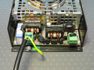
Guardare l’immagine e seguire questi passaggi:
- Inserire il jumper nel connettore phoenix a 2 poli chiamato F1 (sul lato destro dell’amplificatore).
- Collegare la rete (120v) al connettore phoenix CN1 (sul lato sinistro dell’amplificatore)
Vorrei sostituire la ventola del DigiMod, qual è il suo NPN?
Il DigiMod monta una ventola ADDA con cablaggio incluso, prodotta dal nostro fornitore. Si può comprare la sola ventola senza cablaggio e collegare il molex seguendo il pin-out della ventola originale.
Cercare l’NPN: AD0824UB-D90(T)
Per il DigiMod 3000 PFC, qual è il consumo di corrente delle 2 unità che lavorano insieme?
∼7,6A @ 115V
∼4A @ 130V
∼4A @ 230V
Ho un modulo di amplificazione impostato a 230Vac. Appena lo accendo, alimentandolo a 230Vac, la ventola gira per qualche secondo. Se lascio il modulo impostato a 230Vac e lo alimento a 125Vac, la ventola comincia a girare a bassa velocità senza fermarsi. C’è una spiegazione?
Quando il DigiMod viene acceso la ventola gira per qualche secondo, poi riparte solo dopo che è stata superata la soglia limite di temperatura, per raffreddare l’amplificatore. Quando si alimentano 230Vac su un DigiMod impostato a 230Vac, il comportamento della ventola è normale, come descritto nella domanda. Se invece si alimentano 125Vac su un DigiMod impostato a 230Vac, l’alimentatore del modulo prova ad avviare tutto il processo, ma la tensione è più bassa di quella necessaria. In questo caso il microprocessore tenta di avviarsi (e quindi fa girare la ventola), poi, per via dell’assorbimento causato dal tentativo di avvio, il DigiMod raggiunge il valore di tensione che fa scattare la protezione chiamata “undervoltage”. Il comportamento diventa una specie di ciclo, perché il modulo tenta di mettersi in funzione ma non ci riesce, quindi riprova di continuo. Per questo la ventola sembra muoversi di continuo, ma dipende dalla sua inerzia meccanica.
Come devo collegare l’ingresso di segnale al D-Cell504, senza interfaccia di ingresso, se voglio usarlo in configurazione Mono input?
Se si usa il D-Cell504 in configurazione Mono Input, bisogna collegare l’ingresso al canale 1 e al canale 2 in parallelo, seguendo queste istruzioni:
1) Collegare il segnale di ingresso al canale di ingresso 2 sul connettore CN1:
N2- al PIN4
N2+ al PIN5
GND al PIN6
2) Collegare il canale di ingresso 2 in parallelo al canale di ingresso 1 sullo stesso connettore CN1:
PIN5 al PIN22
PIN4 al PIN23
PIN6 al PIN21
BY1 in/out e BY2 in/out sono i pin di ingresso e uscita per collegare un potenziometro esterno che controlla il canale di ingresso, oppure per aggiungere qualcosa come un filtro HP analogico o un attenuatore pad. Per non aggiungere alcun tipo di elaborazione in ingresso, collegare fra loro questi pin:
PIN7 al PIN8
PIN19 al PIN20
Come devo collegare i connettori micro-match dall’interfaccia di ingresso alla scheda DSP-D/C?
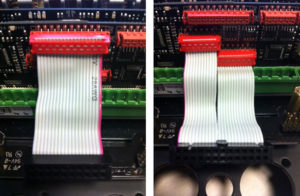
Le immagini qui sotto spiegano come collegare i connettori micro-match. Si può prendere come riferimento il tipo di zoccolo per decidere come orientare il micro-match: un cavo flat ha due connettori micro-match per un totale di 26 poli, l’altro ha un solo connettore micro-match da 20 poli. Attenzione al filo rosso nei cavi flat: serve a individuare qual è il primo pin.
Che differenza c’è fra Lite e Pro Programming Board?
La Lite Programming board permette di memorizzare un preset per volta con SigmaStudio collegato via porta USB. Serve dare un comando “link compile download” e poi premere il pulsante store per salvare il preset appena compilato nello slot preset selezionato dall’interfaccia di ingresso del modulo di amplificazione.
La Pro Programming board è pensata per la produzione di serie: permette infatti di memorizzare un intero pacchetto di 4 preset, ottenuti da una specie di “diffusore master”. Come la Lite Programming Board, il tipo Pro permette di memorizzare un preset per volta nel DSP del diffusore che consideriamo il “master”, sempre usando il PC per dare un comando “link compile download” da SigmaStudio. Oltre alle funzioni in comune con la Lite Programming Board, il tipo Pro permette di memorizzare nella propria memoria EEPROM tutti e 4 i preset appena salvati nel diffusore “master”, in modo da salvare questo pacchetto completo in ogni diffusore che si vuole inizializzare. L’operazione è possibile senza collegamento al PC e senza alimentazione (è il modulo di amplificazione ad alimentare la Pro Programming Board).